Nozzle structure at bottom of refining furnace and nozzle filling method

A technology of refining furnace and bottom water, which is applied in the direction of casting molten material container, metal processing equipment, casting equipment, etc., can solve the problems of increasing material cost, waste of drainage sand, lax fit between sprue and plug, and achieve opening and closing Flexible, improve the utilization rate, and the effect of tight shut-off of the nozzle

Inactive Publication Date: 2009-11-18
INNER MONGOLIA FIRST MACHINERY GRP
View PDF1 Cites 9 Cited by
  • Summary
  • Abstract
  • Description
  • Claims
  • Application Information

AI Technical Summary

Problems solved by technology

The disadvantages of the structure of the sealing nozzle at the bottom of the refining furnace in this patent are: at present, high-alumina cast nozzle bricks are used, and the shape of the inner cavity (nozzle) is a straight-through shape of a horn, and the upper nozzle ( The upper nozzle) chamfer is R90. With the extension of refining time and pouring time, the upper part of the high-aluminum nozzle and the contact part of the plug will be continuously corroded, resulting in poor fit between the nozzle and the plug, resulting in uncontrolled pouring of molten steel Happening
This increases the cost of materials
In addition, the cast iron cover plate is not closely matched with the water outlet, so in order to prevent it from moving, the water outlet needs to be filled with drainage sand around it, which causes waste of drainage sand

Method used


Image

  • Nozzle structure at bottom of refining furnace and nozzle filling method

Examples


Embodiment Construction

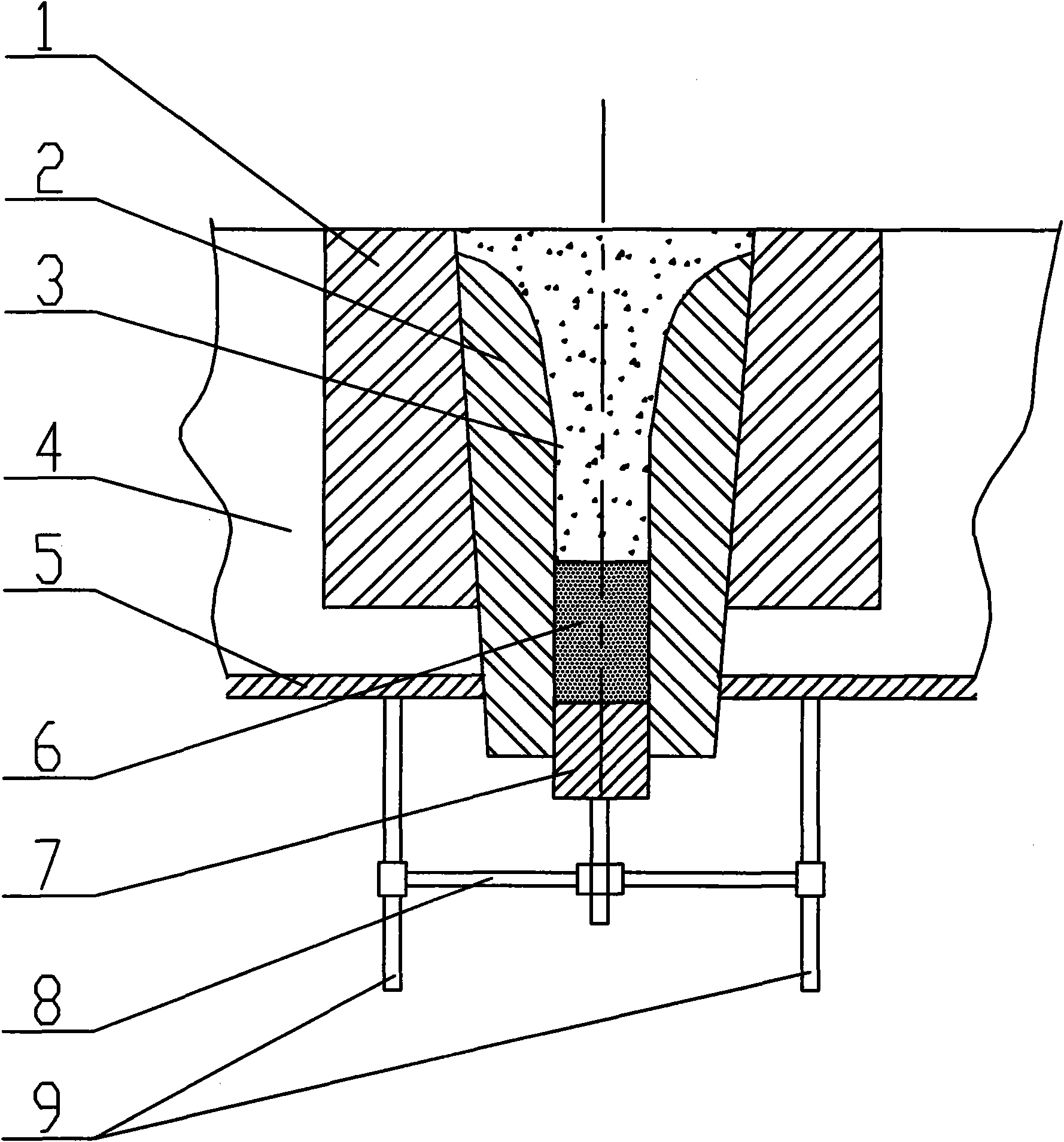
[0013] Refer to attached figure 1 , the nozzle structure at the bottom of the refining furnace of the present invention includes a seat brick 1, a nozzle brick 2, a refractory lining 4, a refining furnace bottom 5, a plug 7, a rotatable bracket 8, and a support 9, and the nozzle brick 2 is produced by Shanghai Taishan Refractory Co., Ltd. It is made of non-fired aluminum-carbon casting mouth brick (aluminum-carbon refractory material with resin as the binder), and the upper chamfer of the inner cavity of the nozzle brick is R58mm.

[0014] The nozzle filling method is as follows: when the lower opening of the nozzle brick inner cavity is blocked and locked by the plug 7, first fill the inner cavity of the nozzle brick with cast iron chips 6 to a height of 100 mm and compact them, and then fill the upper layer of the cast iron chips 6 Drainage sand 3 is tamped to the upper edge of the nozzle brick inner cavity. Drainage sand 3 is made of zirconium drainage sand produced by Hena...


PUM


Abstract

The invention relates to a nozzle structure at the bottom of a refining furnace and a nozzle filling method. The nozzle structure at the bottom of the refining furnace comprises a seating brick, a nozzle brick, refractory lining, a refining furnace base, a plug, a rotatable bracket and a supporting frame, and is characterized in that: the nozzle brick is manufactured by adopting aluminum-carbon refractory material taking resin as bonding agent, and the chamfer angle of the upper mouth of an inner cavity of the nozzle brick is R58mm. The nozzle filling method comprises the following steps: in the situation that the lower mouth of the inner cavity of the nozzle brick is plugged and locked by the plug, cast-iron scrap is filled in the inner cavity of the nozzle brick to the height of 80-120mm and tamped, and then flow guiding sand is filled at the upper layer of the cast-iron scrap to the upper edge of the inner cavity of the nozzle brick and tamped so as to complete the plugging and filling of the nozzle, wherein the flow guiding sand adopts zirconium flow guiding sand. The invention has the advantages that: the aluminum-carbon refractory nozzle brick taking resin as bonding agent can meet the requirement of multi-box casting of the refining furnace, simultaneously the radian at the upper end of the inner cavity of the nozzle brick is changed from R90 to R58, the nozzle is tightly closed in the casting process, and the use of the zirconium flow guiding sand and the improvement of the filling method realize that multi-box casting molten steel of the refining furnace can automatically flow out along with the falling of the flow guiding sand, thus achieving the purpose of automatic casting.

Description

Technical field: [0001] The invention relates to a nozzle structure at the bottom of a refining furnace and a nozzle filling method, belonging to the technical field of steel smelting and pouring. Background technique: [0002] Chinese patent CN1206062C discloses a multi-box pouring system for hot-fill plug rods in refining furnaces. After matching, the molten steel multi-box pouring system is completed. The disadvantages of the structure of the sealing nozzle at the bottom of the refining furnace in this patent are: at present, high-alumina casting nozzle bricks are used, and the shape of the inner cavity (nozzle) is a straight-through shape of a horn, and the upper nozzle ( The upper nozzle) chamfer is R90. With the extension of refining time and pouring time, the upper part of the high-aluminum nozzle and the contact part of the plug will be continuously corroded, resulting in poor fit between the nozzle and the plug, resulting in uncontrolled pouring of molten steel Co...

Claims


Application Information

Patent Timeline
Patent Type & Authority Applications(China)
IPC IPC(8): B22D41/44
Inventor 张秀清高为孙志刚刘峻岭马俊德张挨元王喜爱周玉梅史金彪
Owner INNER MONGOLIA FIRST MACHINERY GRP
Why Eureka
Try Eureka