Double-pole type segregated rotation power-receiving type trolley-pole in transverse and lateral direction

A double pole type, horizontal and lateral technology, applied in the direction of electric vehicles, electric vehicle charging technology, charging stations, etc. Limitation of scope and other issues, to achieve the effect of simple structure, safe operation and use, and beautiful station area

Inactive Publication Date: 2009-11-18
SHANGHAI JIAO TONG UNIV
View PDF1 Cites 8 Cited by
  • Summary
  • Abstract
  • Description
  • Claims
  • Application Information

AI Technical Summary

Problems solved by technology

Although the invention adopts the two-wire pantograph collector pole power receiving method with the tram roof being lifted and lowered, its automatic lifting and lowering of the two-wire pair has less constraints on the network connection, and can be used for the two-wire power receiving and charging of the rechargeable trolleybus in the station area. ; but from its technology "parallelogram linkage" and "when the cylinder on the bottom frame and the bow spring make the lower arm swing, the conductive slide plate on the top of the bow is raised and lowered", and "it can enter and exit the net while the tram is running" It can be seen that the trolleybus collector pole moves up and down when it is working, and its bow-top conductive slide receives power from the special charging feeder network above the vehicle driving road in the overhead station area. Whether it is drawn out through the electric pole on the sidewalk or on the shed of the bus waiting station on the street still restricts the driving of other super-high vehicles such as some engineering vehicles and special transport vehicles, and the charging type trolleybus waiting Therefore, the station area of ​​the station is not beautiful enough; moreover, the parallelogram linkage mechanism composed of the collector pole, the balance pole, the bow head seat crossbar, etc. makes the form and structure of the collector pole complicated, so this kind of technology has defects, and the scope of application is still restricted

Method used


Image

  • Double-pole type segregated rotation power-receiving type trolley-pole in transverse and lateral direction
  • Double-pole type segregated rotation power-receiving type trolley-pole in transverse and lateral direction
  • Double-pole type segregated rotation power-receiving type trolley-pole in transverse and lateral direction

Examples


Embodiment Construction

[0015] The embodiments of the present invention are described in detail below in conjunction with the accompanying drawings: this embodiment is implemented on the premise of the technical solution of the present invention, and detailed implementation methods and specific operating procedures are provided, but the protection scope of the present invention is not limited to the following the described embodiment.

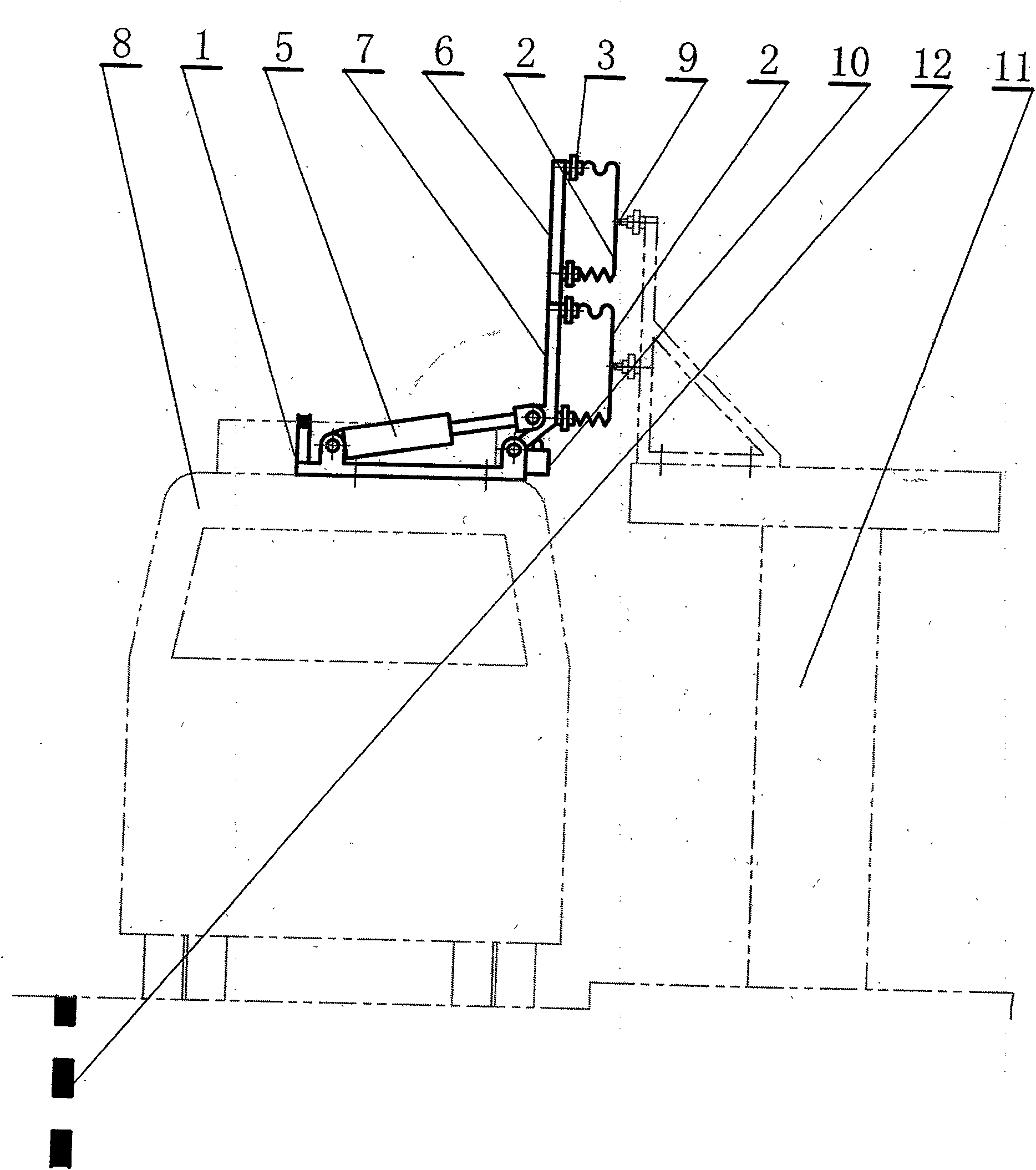
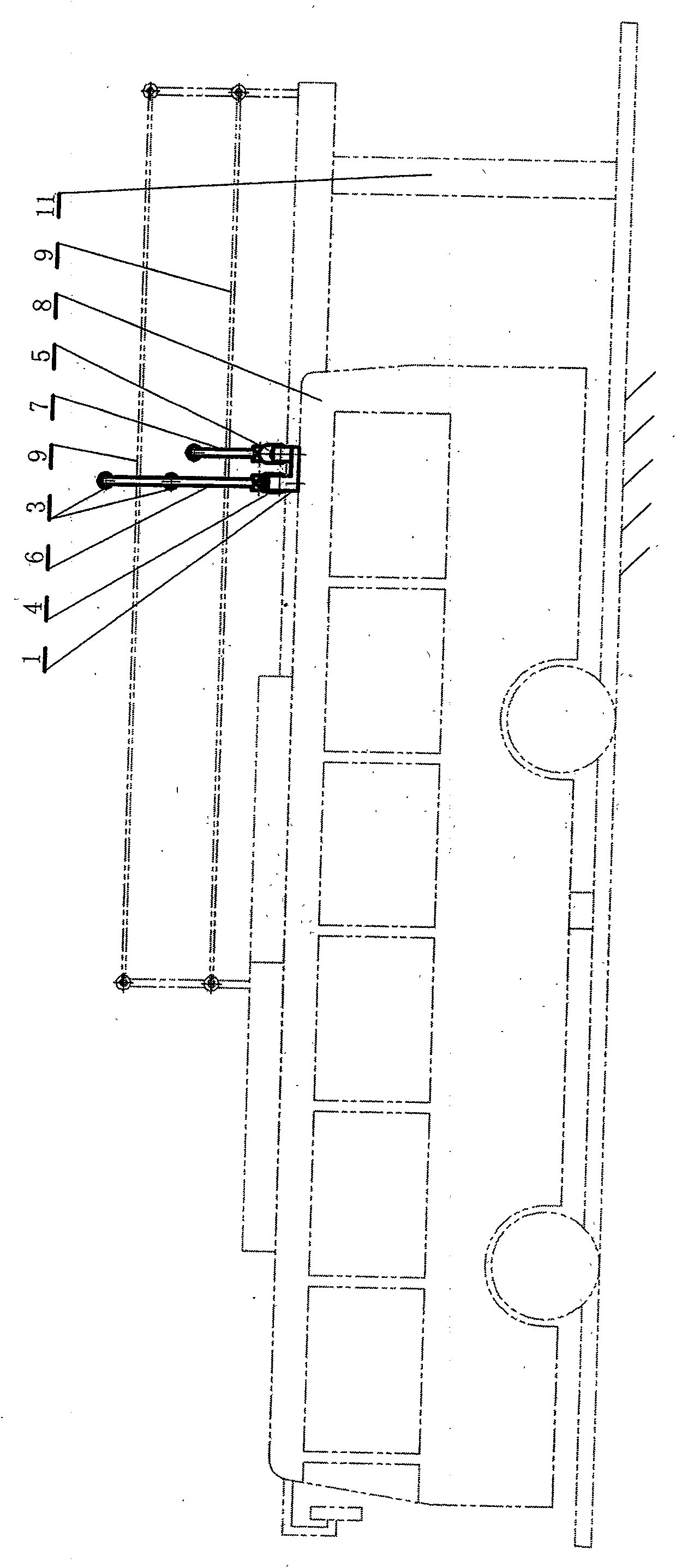
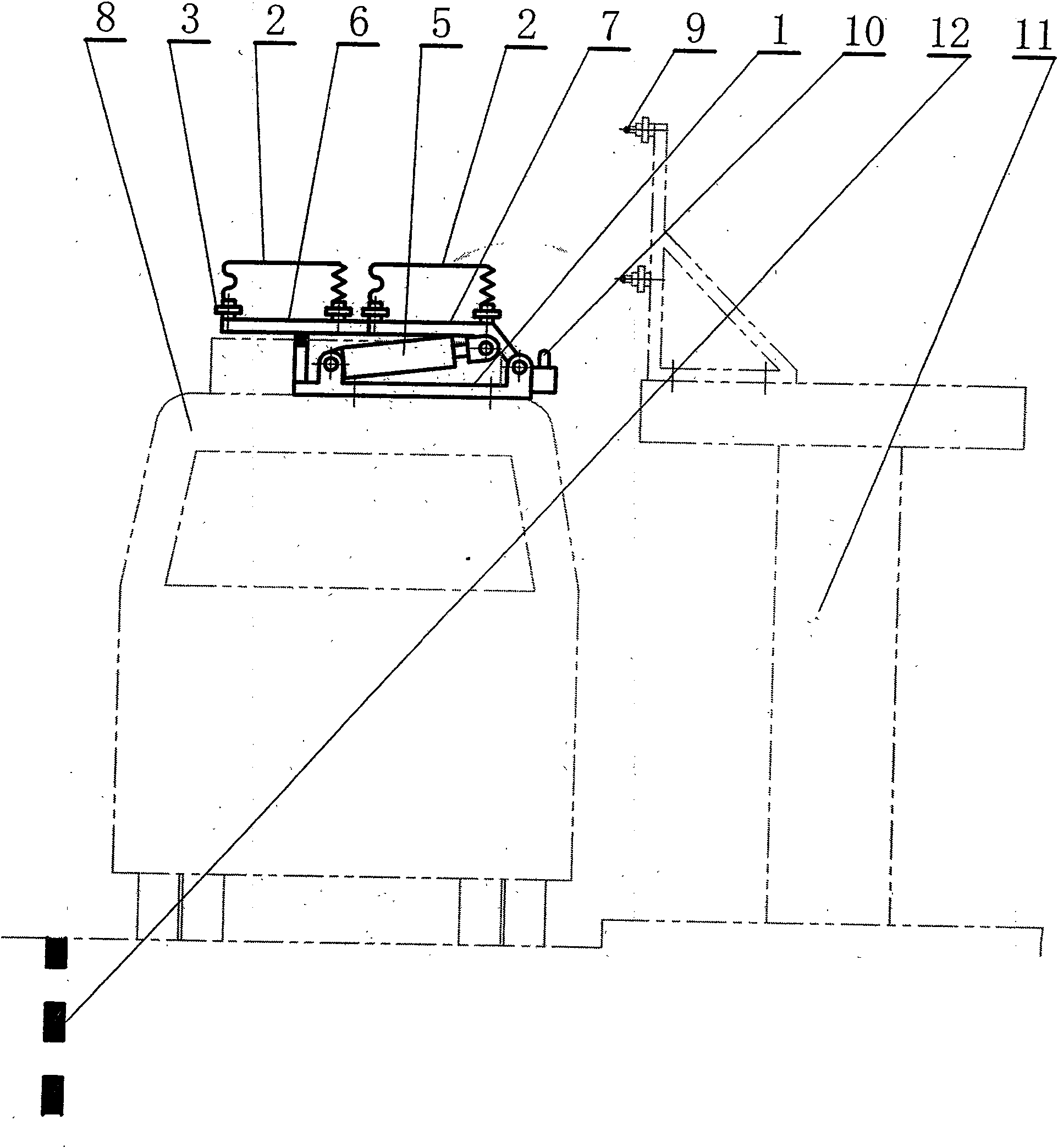
[0016] Such as figure 1, figure 2, image 3 with Figure 4 As shown, this embodiment includes: a base 1, a pantograph body 2, an insulator 3, a first set of lifting bow driving device 4 and a second set of lifting bow driving device 5, a long and a short first bow head support rod 6 and a second Two bow head support rods 7, the receiving rods are two groups, arranged side by side on the roof of the bus 8, the first set of bow-raising drive device 4 and the second set of bow-raising drive device 5 are located on the bus of the bus 8 On the top or on the base 1, t...


PUM


Abstract

The invention relates to a double-pole type segregated rotation power-receiving type public transportation trolley bus trolley-pole in transverse and lateral direction, comprising a chassis, conductive pantograph bodies, an insulator, two sets of lift pantograph driving devices, two pantograph head support bars with one being short and the other being long; two groups of trolley-poles are arranged at the roof of the public transportation trolley bus side by side; the two sets of the lift pantograph driving devices are arranged at the roof of the public transportation trolley bus or at the chassis; the power output ends of the two sets of the lift pantograph driving devices are connected the two pantograph head support bars with one being short and the other being long; the lower ends of the pantograph head support bars are hinged with the chassis; a bi-polar pantograph bodies are respectively supported at the two pantograph head support bars by the insulator; wherein, the conductive pantograph body supported at the longer pantograph head support bar is close to the upper end of the pantograph head support bar; under the effect of the respective lift pantograph driving devices, the two pantograph head support bars respectively rotate and lift in the transverse and lateral plane vertical to the driving direction of the public transportation trolley bus; so that the conductive pantograph bodies thereon can respectively approach and closely contact the double feeding wires. The invention features simple structure, beautiful appearance of the stand and no restrictions imposed upon the passing cars.

Description

technical field [0001] The invention relates to a power receiving device for trams in the technical field of transportation, in particular to a lateral double-rod type split-rotating power receiving pole for bus trams. Background technique [0002] At present, the bus or trolley bus using supercapacitor energy storage in the field of urban public transportation has entered commercial operation or trial operation, and its vehicle has a small amount of supercapacitor, so the vehicle is light in weight, flexible and fast, and only needs to use the terminal and Short-term fast supplementary charging when parking at some intermediate stops can drive uninterrupted on the entire operating line. Since this technology can mostly cancel the original trolleybus overhead power supply contact wire network or feeder wire network along the bus line, only a section of contact wire network dedicated to charging is reserved above the station area of ​​the terminal station and some intermediat...

Claims


Application Information

Patent Timeline
Patent Type & Authority Applications(China)
IPC IPC(8): B60L5/22B60L5/26
CPCB60L11/185B60L5/36B60L11/1816Y02T90/14Y02T90/121Y02T10/7088B60M7/003Y02T10/7005Y02T90/128B60L53/11B60L53/14Y02T10/70Y02T10/7072
Inventor 程晓鸣
Owner SHANGHAI JIAO TONG UNIV
Why Eureka
Try Eureka