Patterning preparation method for nano array

A nano-array and patterning technology is applied in the field of patterning preparation of nano-arrays, which can solve the problems of unsuitable nano-materials, harsh experimental conditions, and low requirements for substrates, and achieves improved field emission performance, simple operation, and easy availability of raw materials. Effect

Inactive Publication Date: 2012-09-05
NANJING UNIV
View PDF5 Cites 0 Cited by
  • Summary
  • Abstract
  • Description
  • Claims
  • Application Information

AI Technical Summary

Problems solved by technology

These methods are complex in process, harsh in experimental conditions, and are not suitable for nanomaterials that have low requirements on the substrate and do not require catalyst-assisted growth.

Method used


Image

  • Patterning preparation method for nano array
  • Patterning preparation method for nano array
  • Patterning preparation method for nano array

Examples


Embodiment 1

[0053] Example 1 Using anhydrous AlCl 3 A patterned AlN nanocone array was fabricated using the precursor and Mo mesh as a mask.

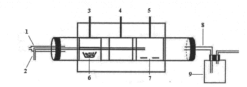
[0054] Anhydrous AlCl 3 Placed in a three-section tube temperature control furnace (such as figure 1 In the low-temperature reaction zone of ), the quartz tube with the Si wafer covered with 150 mesh Mo mesh is placed in the medium-temperature deposition zone, repeatedly filled with argon gas and evacuated by mechanical pump 2-3 times, under the protection of Ar gas (100sccm), At the same time, the temperature of the reaction chamber in the low temperature zone, the middle temperature zone and the high temperature zone are respectively increased to 130°C, 650°C, and 1100°C (the heating rate is 10°C / min). Then enter NH separately and at the same time 3 (20sccm) and Ar gas (300sccm), AlCl 3 After sublimation, it is transported to the deposition area and NH under the drive of Ar gas. 3 After mixing and reacting, the resulting AlN is deposited on the subst...

Embodiment 2

[0057] Example 2 Using anhydrous AlCl 3 A patterned AlN nanocone array was fabricated using the precursor and Mo mesh as a mask.

[0058] Anhydrous AlCl 3 Placed in the low-temperature reaction zone of a three-stage tubular temperature-controlled furnace, placed a quartz tube covered with a 150-mesh Mo mesh in the deposition zone at a medium temperature, repeatedly filled with argon gas and evacuated 2-3 times with a mechanical pump. Under the protection of air (100sccm), the temperature of the reaction chamber in the low temperature zone, middle temperature zone and high temperature zone was raised to 140℃, 780℃, 1100℃ (heating rate is 10℃ / min). Then enter NH separately and at the same time 3 (20sccm) and Ar gas (300sccm), AlCl 3 After sublimation, it is transported to the deposition area and NH under the drive of Ar gas. 3 After mixing and reacting, the resulting AlN is deposited on the substrate. The reaction lasts for 4 hours, and is naturally cooled to room temperature under...

Embodiment 3

[0059] Example 3 A patterned AlN nanocone was prepared using Al powder as a precursor.

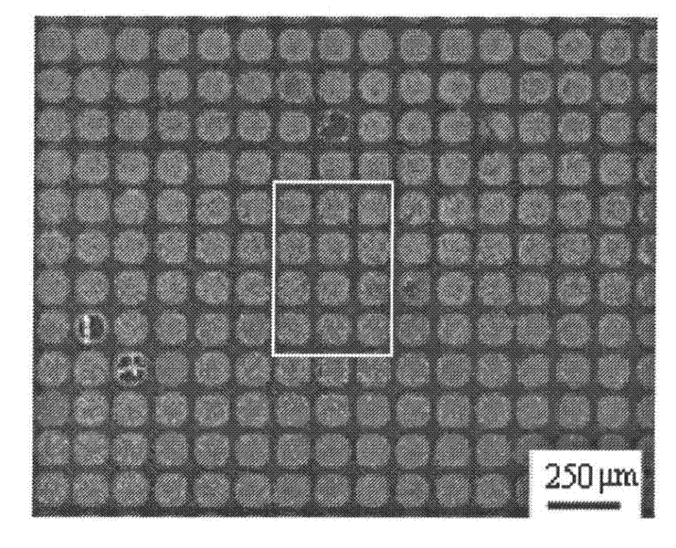
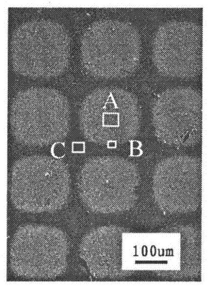
[0060] Place Al in the high temperature reaction zone of a tubular temperature control furnace, place the Si substrate covered with Mo mesh on the Al powder 0.5-5cm above the Al powder, repeatedly fill with argon and evacuated with a mechanical pump 2-3 times, in Ar gas ( Under the protection of 100sccm), the temperature of the reaction chamber in the high temperature zone was increased to 1100°C (the temperature rise rate was 10°C / min). Then pass into NH 3 / N 2 (200sccm) and Ar gas (300sccm), Al and NH 3 / N 2 The reaction produces AlN. The reaction lasts for 4 hours, and is naturally cooled to room temperature under the protection of Ar gas (100sccm), and the Mo mesh is stripped to obtain patterned AlN nanomaterials, such as Figure 14-16 Shown.


PUM

PropertyMeasurementUnit
diameteraaaaaaaaaa
diameteraaaaaaaaaa

Abstract

The invention relates to a patterning preparation method for a nano array, which is simple and practical and does not need the aid of a catalyst. The patterning preparation method for the nano array deposits a nano array material on a substrate using a metal mesh as a mask. The method can be used for patterning growth of various nano materials, and select proper mask material and specification according to reaction conditions (temperature, atmosphere and the like) and experimental requirements to deposit and synthesize the nano array material on various substrates. Compared with the prior technical routes such as substrate surface modification, electron beam etching technology, magnetron sputtering and the like, the method has the advantages that the method does not need chemical substances to pre-treat the substrate, is environment-friendly, does not need harsh experimental conditions, has low cost, does not need complex process, and has simple operation; raw materials are easily obtained, and grids of various specifications have commercial products; and the method also can be used for preparing various patterning distributed nano array materials in large area.

Description

Technical field [0001] The invention relates to a patterned preparation method of a nano array, and belongs to a patterned growth technology of nano materials. Background technique [0002] Cold cathode field emission materials have a wide range of potential applications in military and national life, such as mass spectrometry, ion engines, accelerators, parallel electron beam etching, X-ray imaging, solid state light sources, vacuum microelectronic devices, etc. field. In recent years, related research has mainly focused on the application of cold cathode field emission materials in field emission flat panel displays (N.S. Xu, S.E. Huq, Mater. Sci. Eng. R 2005, 48, 47). The development of cold cathode field emission materials has gone through three eras: after a voltage is applied to the cone-shaped material, its tip will generate a strong electric field, which is easy to induce electron emission. In the late 1960s, Spindt cone-shaped materials (molybdenum and The cold cathode...

Claims


Application Information

Patent Timeline
Patent Type & Authority Patents(China)
IPC IPC(8): B82B3/00C23C16/04C23C16/34
Inventor 刘宁吴强王喜章胡征
Owner NANJING UNIV
Why Eureka
Try Eureka