
Oil and gas separating system embedded in valve chamber cover

A separation system and valve chamber technology, applied in the field of oil and gas separation systems, can solve problems such as insufficient oil and gas separation, and achieve the effects of low cost and small layout space

Inactive Publication Date: 2009-11-18
CHERY AUTOMOBILE CO LTD
View PDF1 Cites 8 Cited by
  • Summary
  • Abstract
  • Description
  • Claims
  • Application Information

AI Technical Summary

Problems solved by technology

[0003] The purpose of the present invention is to provide an oil-gas separation system built in the valve chamber cover to solve the problem of insufficient oil-gas separation in the current oil-gas separation system

Method used


Image

  • Oil and gas separating system embedded in valve chamber cover
  • Oil and gas separating system embedded in valve chamber cover
  • Oil and gas separating system embedded in valve chamber cover

Examples


Embodiment 1

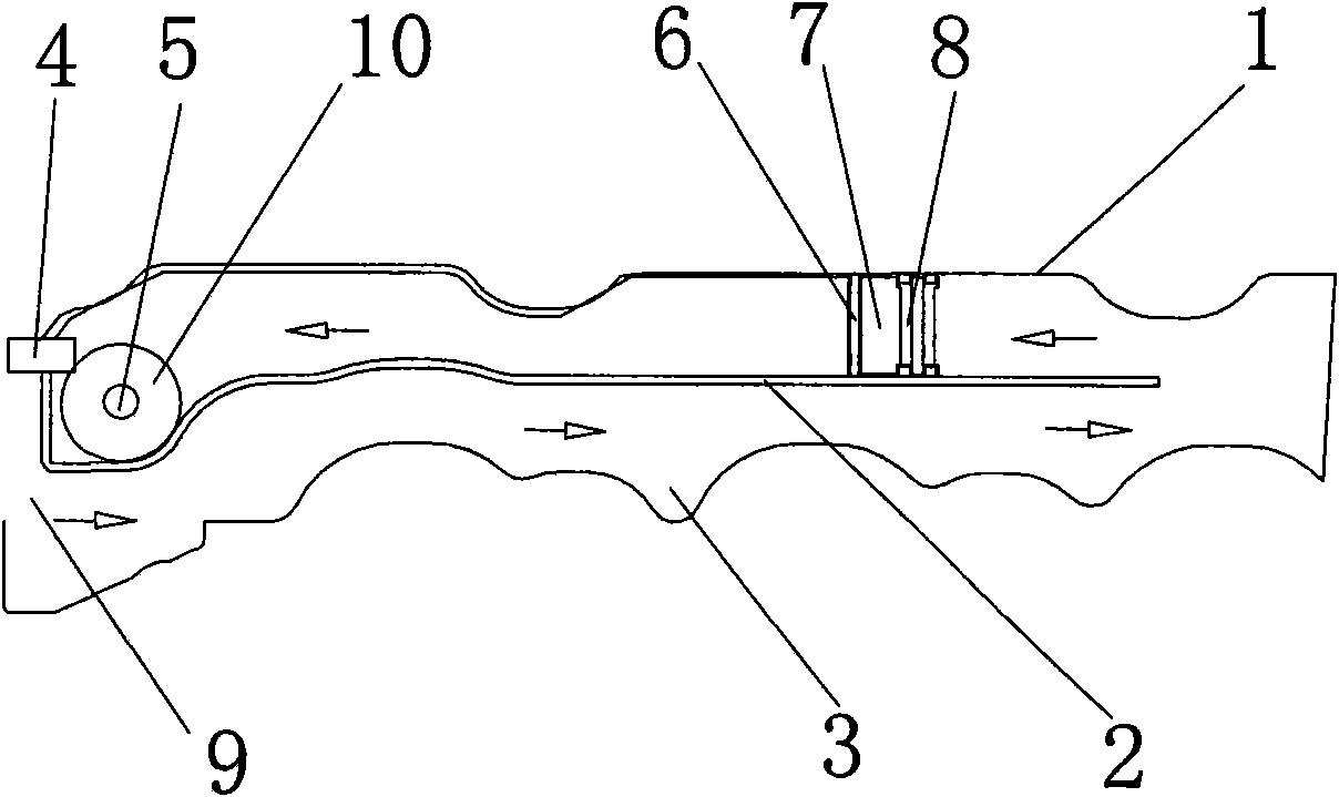
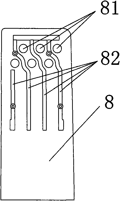
[0013] Example 1, such as figure 1 , 2 As shown in , 3, an oil-gas separation system built in the valve chamber cover, the oil-gas passage structure is divided into upper and lower layers by the partition plate 2 in the housing 1, and the lower layer includes the oil-gas inlet 9 and the labyrinth 3 for pre-separated oil and gas , the upper layer includes the filter unit for the main separation of oil and gas and the oil and gas outlet 4. The filter unit includes a filter plate 8 and a filter 7 arranged in sequence. The filter 7 is mainly composed of sponge-like or wool brush-like items, and is installed behind the filter plate 8. Behind the filter is a baffle that can pass oil and gas. Plate 6 is fixed. The filter plate 8 is provided with a group of oil and gas filter holes 81 and a group of impact plates 82 for oil return collection.

Embodiment 2

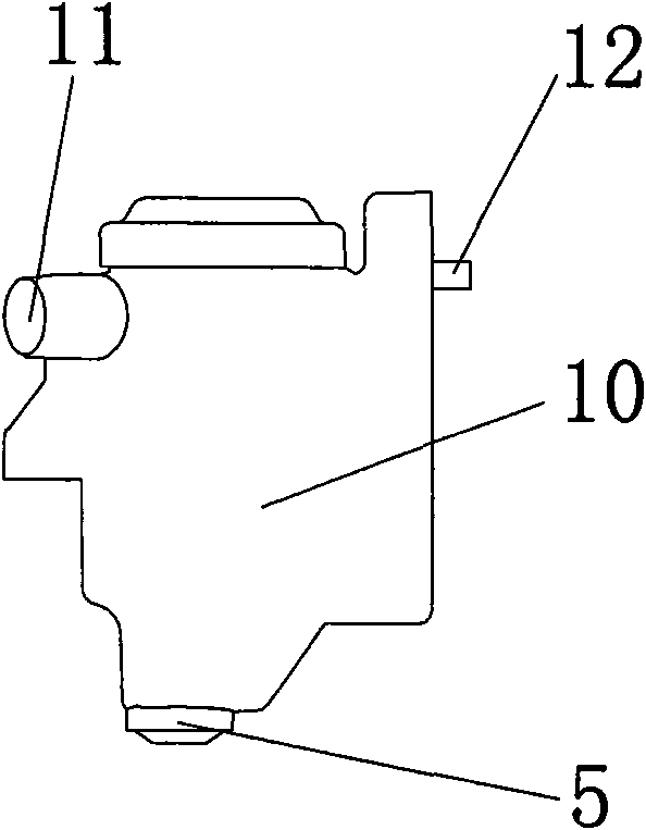
[0014] In Embodiment 2, in order to further separate oil and gas, a PCV valve 10 is provided behind the filter unit for the main separation of oil and gas. All the other are with embodiment 1. The PCV valve 10 includes an oil and gas inlet 12 , an oil and gas outlet 11 and an oil return port 5 .

[0015] The structure of the PCV valve is a one-way valve type, and the control pressure range is -3 ~ 1Kpa; the filter is a filter device similar to sponge or wool brush; the specific structure of the filter plate is to set the filter The impact plate of the hole is formed, the thickness of the impact plate is 1-4mm, and the diameter range of the filter hole is 1.5-5mm.

[0016] The working process of the present invention is, as figure 1 As shown, the oil and gas mixture enters the labyrinth for pre-separation from the oil and gas inlet, and then passes through the filter unit composed of filter plates and filters for main separation. The entire oil and gas separation system adopt...


PUM

PropertyMeasurementUnit
Thicknessaaaaaaaaaa

Abstract

An oil and gas separating system embedded in a chamber cover is divided into oil and gas passage structures of an upper layer and a lower layer in a shell, wherein the lower layer comprises an oil and gas inlet and a labyrinth for pre-separating the oil and the gas; the upper layer comprises a filter unit mainly used for separating the oil from the gas and an oil and gas outlet; the oil and gas separating system is characterized in that the filter unit comprises a filter plate and a filter that are sequentially arranged; the filter mainly consists of a sponge-like or wool-brush-like article and is arranged on the rear surface of the filter plate; and the rear surface of the filter can be fixed by a baffle through which the oil and the gas can pass. In order to separate the oil from the gas further, a PCV valve is arranged behind the filter unit used for separating the oil and the gas mainly. The filter plate is provided with a group of oil and gas filter holes and a group of striking plates playing a role of collecting returned oil. As the oil and gas pre-separation is carried out through the labyrinth and the main separation is carried out by the filter unit consisting of the filter plate and the filter, the separated machine oil can flow back on the cylinder cover by a PCV valve oil release chamber for reusing, the oil and gas separation efficiency of the oil and gas separating system achieves about 80%, the arrangement space is small, the cost is low relatively and the oil and gas separating system is applicable to current high-end engines.

Description

technical field [0001] The invention relates to an oil-gas separation system, in particular to an oil-gas separation system built in an engine valve chamber cover. Background technique [0002] At present, the cover of the valve chamber of the automobile engine generally uses a labyrinth and a partition to separate oil and gas. The oil and gas mixture is separated from the oil and gas through the labyrinth, and then the separated oil is discharged into the cylinder head through the oil return pipe on the partition, and the gas flows out through the labyrinth. . Chinese patent application number CN200510061317.7 discloses a labyrinth oil-gas separation device. In this design, part of the oil and gas in the oil and gas separation space flows away before it collides with the baffle, resulting in insufficient condensation of oil, insufficient oil and gas separation, and low oil and gas separation efficiency. Contents of the invention [0003] The object of the present invent...

Claims


Application Information

Patent Timeline
IPC IPC(8): F01M11/08
Inventor 关迪
Owner CHERY AUTOMOBILE CO LTD
Features
  • Generate Ideas
  • Intellectual Property
  • Life Sciences
  • Materials
  • Tech Scout
  • Unparalleled Data Quality
  • Higher Quality Content
  • 60% Fewer Hallucinations
Learn More