
Water pump control method and water pump control system in rail vehicle water supply system

A technology for water supply systems and rail vehicles, applied in the field of water pump control methods and control systems, to achieve the effect of preventing leakage problems and improving winter antifreeze ability

Active Publication Date: 2012-07-04
CRRC QINGDAO SIFANG CO LTD +1
View PDF6 Cites 0 Cited by
  • Summary
  • Abstract
  • Description
  • Claims
  • Application Information

AI Technical Summary

Problems solved by technology

[0002]The water pump control of the existing rail vehicle water supply system mainly relies on the flow switch of the water pump itself to control the flow of the water pump and the working state of the water pump. When someone is using the water supply terminal on the vehicle, the water pump works to supply water to the vehicle. However, when no one is using the water supply terminal on the vehicle, the water pump will stop working. At this time, the water in the pipeline will be in a static state. In winter, the water in the pipeline will freeze, eventually causing the pipeline to be blocked, and the water on the vehicle cannot be used. In addition, when the water supply terminal on the vehicle is damaged, or someone maliciously uses water, the existing water pump control system cannot detect this. The water pump will supply water to the car all the time, resulting in a great waste of water resources
The existing water pump control system has poor antifreeze and no anti-leakage function

Method used


Image

  • Water pump control method and water pump control system in rail vehicle water supply system
  • Water pump control method and water pump control system in rail vehicle water supply system

Examples


Embodiment Construction

[0023] Below in conjunction with accompanying drawing and specific embodiment the present invention is described in further detail:

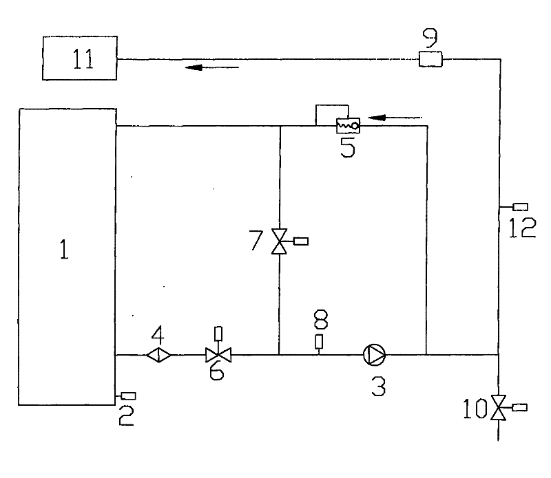
[0024] Such as figure 1 As shown, the water pump control system in the rail vehicle water supply system of the present invention includes: a water tank 1, a water pump 3 for supplying water to the vehicle is set in the water supply pipeline, and a water pump 3 is set at the water outlet of the water tank 1 The filter 4 is used for filtering and cleaning the water entering the water pump 3 .

[0025] A liquid level switch 2 is provided at the position near the bottom of the water tank 1, and a water sensor switch 8 is also provided on the water supply pipeline between the water outlet of the water tank 1 and the water pump 3. The liquid level switch 2 is used to detect water in the water tank 1. Liquid level, the water sensor switch 8 is used to detect whether there is water flowing in the water supply pipeline, whether there is no water in the...


PUM


Abstract

The invention relates to a water pump control method and a water pump control system in a rail vehicle water supply system for controlling a water pump to continuously operate. When tail-end water equipment on a vehicle is closed, water pumped by the water pump flows back to a water tank through a bypass pipeline. When the water pump control system is powered down, the water pump stops operating,a water supply pipeline is cut off, and stored water in the water supply pipeline is drained out of the vehicle by opening a draining pipeline. The water pump control system comprises a process of detecting the state of continuous water flow in the water supply pipeline so as to further judge whether the water supply pipeline has leakage or not. The control system ensures that the water pump can be continuously operated regardless of whether the tail-end water equipment on the vehicle is used or not by arranging the bypass pipeline and a bypass valve and guarantees that the water supply pipeline cannot be frozen in winter. Moreover, the control system is also additionally provided with the draining pipeline and a draining electromagnetic valve so as to guarantee that when the control system is powered down and the water pump does not work, the water in the water supply pipeline can be completely drained out of the vehicle and cannot be stored in the water supply pipeline, thereby the antifreezing capacity of the water pipeline in a pump room in winter is improved.

Description

technical field [0001] The invention relates to a water pump control method and a control system, in particular to a water pump control method and a control system suitable for rail vehicle water supply systems. Background technique [0002] The water pump control of the existing rail vehicle water supply system mainly relies on the flow switch of the water pump itself to control the flow of the water pump and the working state of the water pump. When someone is using the water supply terminal on the car, the water pump works to supply water to the car. , However, when the water supply terminal on the car is unused, the water pump will stop working. At this time, the water in the pipeline will be in a static state. If it is in winter, the water in the pipeline will freeze, and finally the pipeline will be damaged. In addition, when the water supply terminal on the car is damaged, or someone maliciously uses water, the existing water pump control system cannot detect this si...

Claims


Application Information

Patent Timeline
Patent Type & Authority Patents(China)
IPC IPC(8): G05B19/048E03B7/12
Inventor 孙彦陈建国邱业
Owner CRRC QINGDAO SIFANG CO LTD
Learn More