
Card with image display function

A technology of image display and function, which is applied in the direction of recording carriers used in machines, optics, instruments, etc., and can solve problems such as inability to precisely configure wiring terminals, inability to realize liquid crystal units, thermal deformation, etc.

Inactive Publication Date: 2009-11-18
NISHIYAMA STAINLESS CHEMICAL KK
View PDF4 Cites 0 Cited by
  • Summary
  • Abstract
  • Description
  • Claims
  • Application Information

AI Technical Summary

Problems solved by technology

[0004] However, plastics are inferior to glass in terms of chemical resistance and heat resistance. In particular, since they are inferior to glass in heat resistance, thermal deformation occurs during the manufacturing process and wiring terminals cannot be precisely arranged. The problem
Especially for a liquid crystal unit mounted in an IC card, since the wiring pattern or internal components have to be extremely miniaturized, a commercially viable liquid crystal unit cannot be realized as long as a plastic substrate is used.

Method used


Image

  • Card with image display function
  • Card with image display function
  • Card with image display function

Examples


Embodiment Construction

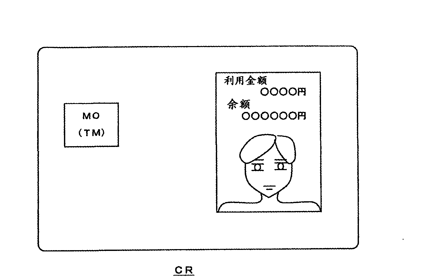
[0030] Hereinafter, the present invention will be described in more detail based on examples. figure 1 It is an external view of the IC card related to the first embodiment, and here, a contact type IC card used as a credit card is illustrated.

[0031] Such as figure 1 As shown in , the IC card CR of this embodiment is configured by disposing the IC module MO on the upper left of the card and disposing the liquid crystal unit LCD on the right side of the card. Since the IC card CR is a contact type, the connection terminal portion TM is formed on the upper surface of the IC module MO. Furthermore, the reason for disposing the liquid crystal unit LCD at a position other than the central position is to make it difficult for the effect to reach the liquid crystal unit LCD even when a force in a bending direction is applied to both ends of the IC card CR.

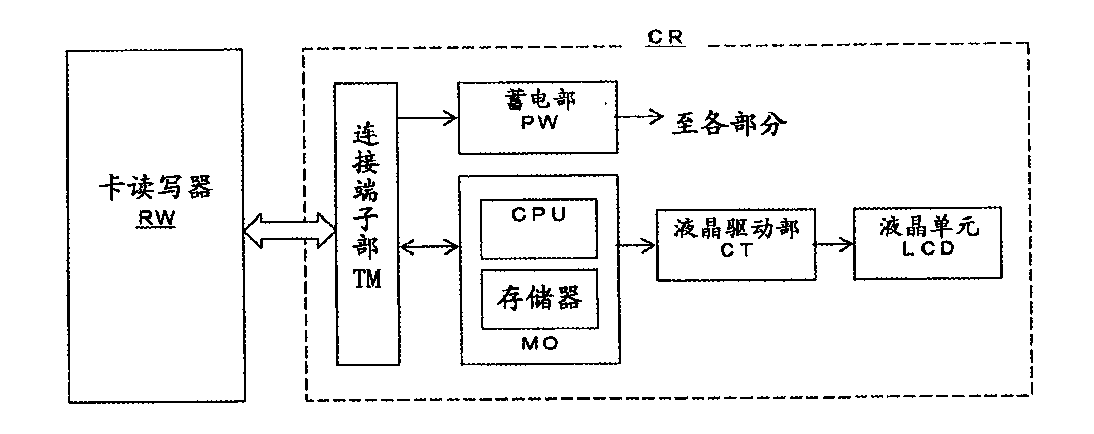
[0032] figure 2It is a block diagram showing the internal structure of the IC card CR. The IC card CR is composed of th...


PUM

PropertyMeasurementUnit
thicknessaaaaaaaaaa
bending strengthaaaaaaaaaa

Abstract

The invention relates to a card CR with image display function, which comprises a central control unit MO, a liquid crystal cell LCD and a power supply unit PW, wherein the central control unit MO controls all work including data transmitting, receiving and processing with an outer device RW, the liquid crystal cell LCD displays necessary information according to instructions from the central control unit MO and the power supply unit PW supplies electricity to each part of the card CR. A first glass plate G1 exposed to users and a second glass plate G2 not exposed to users are attached to the liquid crystal cell LCD, and the total thickness of the two glass plates is less than or equal to 0.60 mm. The lateral surfaces of the peripheral edges of the second glass plate G2 are separated by physical cutting, while mechanical erosion makes the surfaces of cutting-in lines formed by physical cutting at the peripheral edges of the first glass plate G1 smooth. According to the invention, a card with image display function, which is provided with a high-strength LCD panel, can be produced.

Description

technical field [0001] The present invention relates to an IC card having an image display function, and particularly relates to an IC card using a display element such as a liquid crystal cell or organic EL having excellent strength. Background technique [0002] Compared with magnetic cards and the like, IC cards not only have a large memory capacity but also have the advantages of computing functions. However, it is a big problem that the storage content of the memory cannot be confirmed visually, and therefore an IC card with an image display function has been developed (Patent Document 1 (JP-A-2003-270657)). [0003] In this invention, a liquid crystal cell using a plastic substrate instead of a glass substrate is proposed in consideration of card bending deformation. [0004] However, plastics are inferior to glass in terms of chemical resistance and heat resistance. In particular, since they are inferior to glass in heat resistance, thermal deformation occurs during ...

Claims


Application Information

Patent Timeline
Patent Type & Authority Applications(China)
IPC IPC(8): G06K19/077G02F1/1333
Inventor 西山智弘
Owner NISHIYAMA STAINLESS CHEMICAL KK
Learn More