
Electromagnetic wire coil, manufacturing method thereof and induction cooker with wire coil

A manufacturing method and technology of electromagnetic wire, applied in the field of induction cooker and induction cooker, can solve the problems of increasing the assembly operation process, cannot be realized at the same time, reducing work efficiency, etc., so as to reduce the process of assembling the magnetic strip, and reduce the production cost and material cost of the product. , the effect of improving energy efficiency

Inactive Publication Date: 2009-11-18
JOYOUNG CO LTD
View PDF0 Cites 22 Cited by
  • Summary
  • Abstract
  • Description
  • Claims
  • Application Information

AI Technical Summary

Problems solved by technology

The above-mentioned methods are to improve the performance of the induction cooker and induction cooker through external means, and the above-mentioned increase of coil material, increase of anti-magnetic leakage ring or selection of magnetic materials with high permeability to make magnetic strips are inevitable. It will bring about the problems of increased cost, increased assembly operation process, complex process, and reduced work efficiency. In addition, the above three methods generally cannot achieve the effects of improving thermal efficiency and reducing magnetic radiation at the same time.

Method used


Image

  • Electromagnetic wire coil, manufacturing method thereof and induction cooker with wire coil
  • Electromagnetic wire coil, manufacturing method thereof and induction cooker with wire coil
  • Electromagnetic wire coil, manufacturing method thereof and induction cooker with wire coil

Examples


Embodiment Construction

[0018] The technical solutions of the present invention will be further described below in conjunction with the accompanying drawings and embodiments.

[0019] like figure 1 As shown, it is the first embodiment of the electromagnetic wire reel of the present invention. The electromagnetic wire reel includes a wire reel frame 1 and a coil 2. Compared with the existing electromagnetic wire reel, the electromagnetic wire reel cancels the magnetic strip. The setting is to achieve the effect of magnetic concentration by dispersing and setting magnetic objects in the wire tray rack.

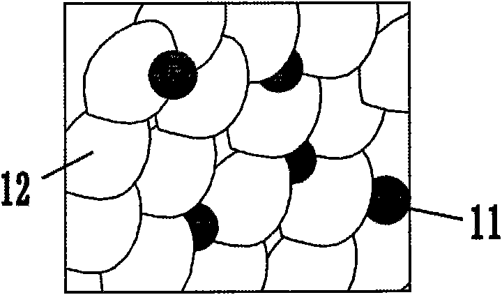
[0020] like image 3 As shown, it is a schematic diagram of the internal structure of the electromagnetic wire reel rack 1 of the present invention. The wire reel rack 1 includes magnetic objects 11 and rack material 12 . The wire reel frame 1 can be prepared by the following method: firstly mix the magnetic substance 11 and the adhesive in a certain proportion, then mix the magnetic object 11 mixed...


PUM

PropertyMeasurementUnit
thermal efficiencyaaaaaaaaaa

Abstract

The invention provides an electromagnetic wire coil, which comprises a wire coil rack and a wire coil; and granular or powdery magnetic substances are dispersed in the wire coil rack. Another aim of the invention is to provide a method for manufacturing the electromagnetic wire coil and an induction cooker. By directly adding the magnetic substances to the wire coil rack, the electromagnetic wire coil makes the wire coil rack act as an original magnetic bar, and can cancel all the magnetic bars used in the prior art; and for the action of the magnetic substances, magnetic lines are collected so as to promote thermal efficiency and reduce magnetic leakage and electromagnetic radiation. In addition, as the setting of the magnetic bars can be cancelled, the wire coil reduces the cost and the working procedure of assembling the magnetic bars; the wire coil rack is directly molded in an injection mode or the magnetic substances are extruded into the wire coil rack by an external force extrusion mode; and compared with the prior art, the electromagnetic wire coil is easier to process and reduces the production cost and the material cost of products.

Description

technical field [0001] The invention relates to the technical field of an electromagnetic cooker and an electromagnetic cooker, in particular to an electromagnetic wire reel and a manufacturing method of the electromagnetic wire reel, and also relates to an electromagnetic cooker with the electromagnetic wire reel. Background technique [0002] The "Implementation Rules for Household Induction Cooker Energy Efficiency Labeling" promulgated by the relevant state departments requires that from March 1, 2009, manufacturers are required to affix energy efficiency labels on the surface of induction cookers and induction cooker products, and products without energy efficiency labels are not allowed. production and sales. In addition, due to the improvement of consumers' requirements for environmental protection and health, manufacturers of induction cookers and induction cookers are prompted to research a new generation of high-efficiency electromagnetic coils in order to reduce r...

Claims


Application Information

Patent Timeline
Patent Type & Authority Applications(China)
IPC IPC(8): H05B6/36B29C45/00B29D31/00B29C70/64F24C7/06B29D99/00
Inventor 朱泽春许立特乔中义
Owner JOYOUNG CO LTD
Learn More