Clutch arrangement
A clutch and pipeline arrangement technology, applied in clutches, fluid-driven clutches, non-mechanical-driven clutches, etc., can solve the problems of lip seal lagging and total failure, and achieve the effect of simplification of assembly
- Summary
- Abstract
- Description
- Claims
- Application Information
AI Technical Summary
Problems solved by technology
Method used
Image

Examples
Embodiment Construction
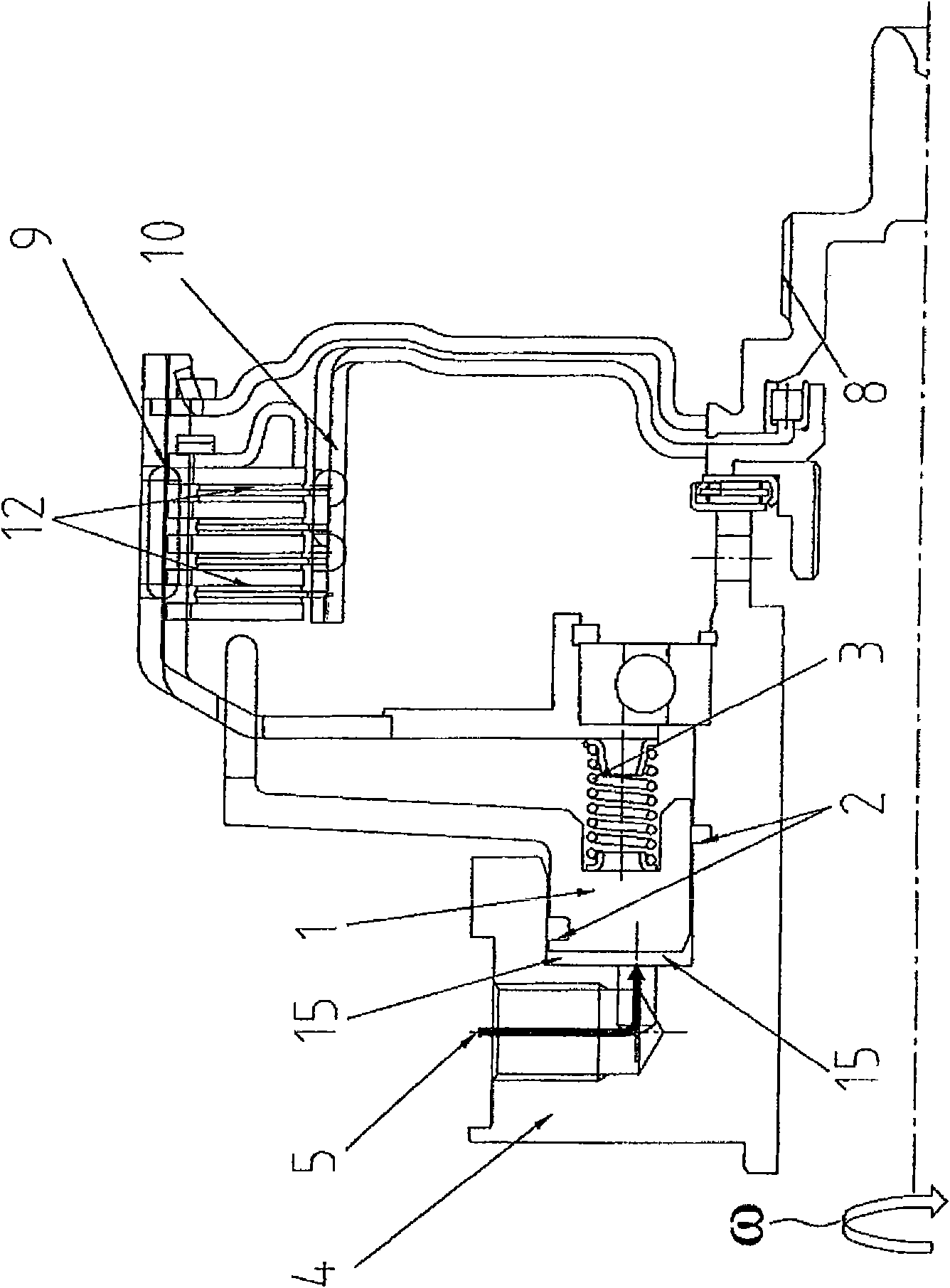
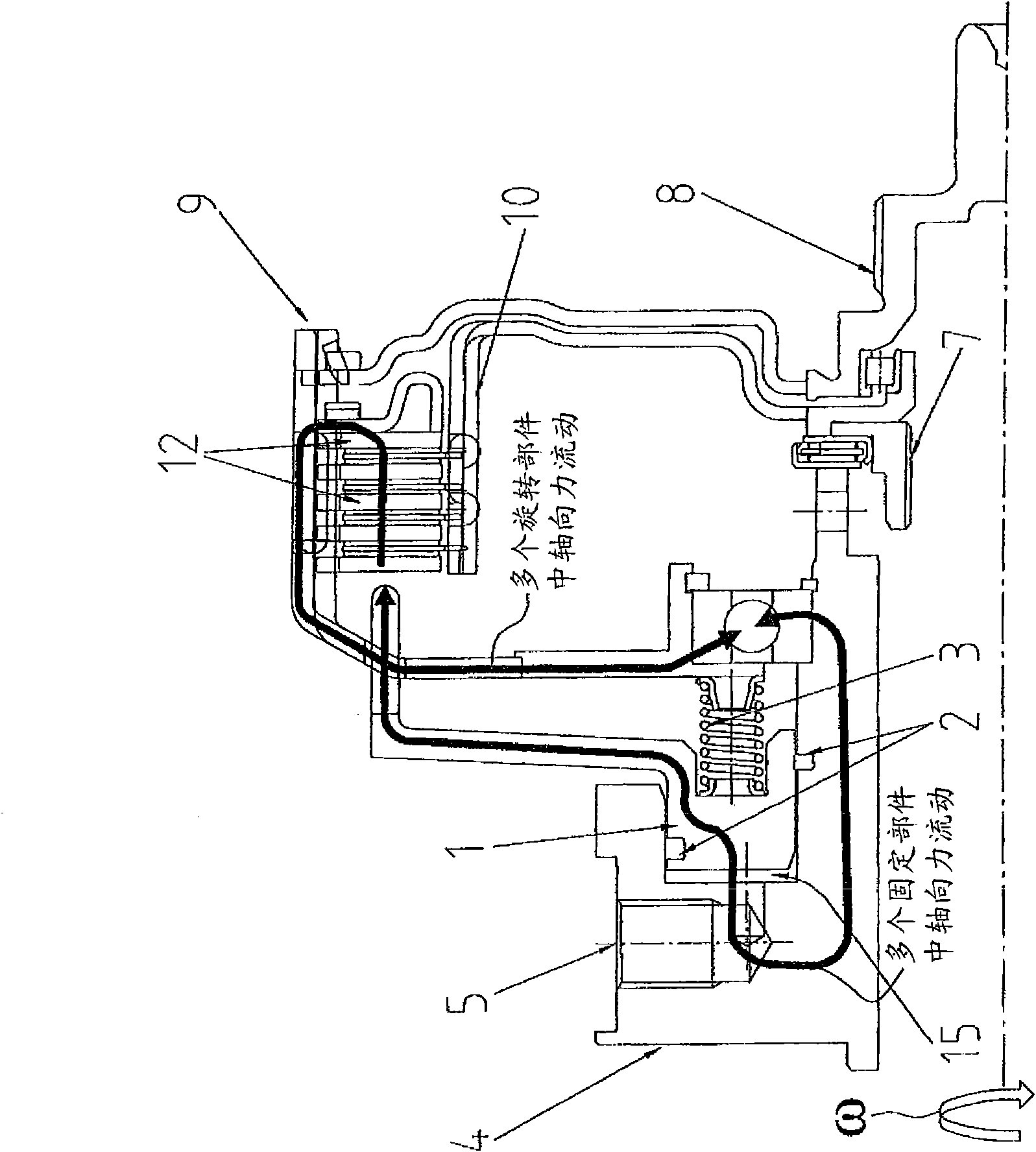
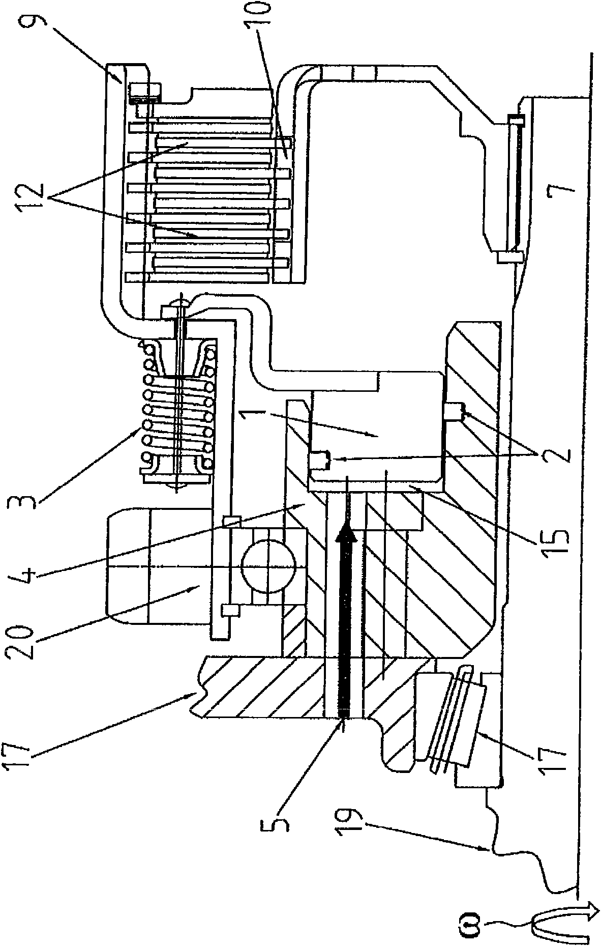
[0024] as by figure 1 and in another Figure 2 to Figure 6 As can be seen in , in a multi-plate clutch, the engine torque is transmitted via a drive flange 8 to a drive side plate carrier 9 . By applying an axial force to a plate assembly 12 arranged in the drive side plate support 9, a frictional torque is exerted in the plate assembly 12 by means of the hollow cylindrical or annular piston 1 embodied as a clutch actuating piston. is transferred to a transmission side plate bracket 10. Said parts are fixedly mounted in a rotational sense together with the drive flange 8 on a drive shaft such that said parts rotate about a common axis of rotation ω. The drive shaft and through it the drive flange 8, the drive shaft side plate bracket 9, the plate assembly 12, the transmission side plate bracket 10 and the piston 1 can thus be arranged to rotate together within the housing of a clutch arrangement of the type described.
[0025] In a conventional manner, the piston 1 protrud...
PUM
 Abstract
Description
Claims
Application Information
 - Generate Ideas
- Intellectual Property
- Life Sciences
- Materials
- Tech Scout
- Unparalleled Data Quality
- Higher Quality Content
- 60% Fewer Hallucinations
Browse by: Latest US Patents, China's latest patents, Technical Efficacy Thesaurus, Application Domain, Technology Topic, Popular Technical Reports.
© 2025 PatSnap. All rights reserved.Legal|Privacy policy|Modern Slavery Act Transparency Statement|Sitemap|About US| Contact US: help@patsnap.com