Detector apparatus and pre-concentrators

A pre-concentrator and detector technology, applied in the field of detector equipment, can solve the problems of low signal-to-noise ratio and difficult realization of reliable detection

Inactive Publication Date: 2009-11-18
SMITHS DETECTION WATFORD LTD
View PDF1 Cites 4 Cited by
  • Summary
  • Abstract
  • Description
  • Claims
  • Application Information

AI Technical Summary

Problems solved by technology

When the sample analyte has only a small concentration in the sample gas, there is a relatively low signal-to-noise ratio, which makes reliable detection difficult to achieve

Method used


Image

  • Detector apparatus and pre-concentrators
  • Detector apparatus and pre-concentrators

Examples


Embodiment Construction

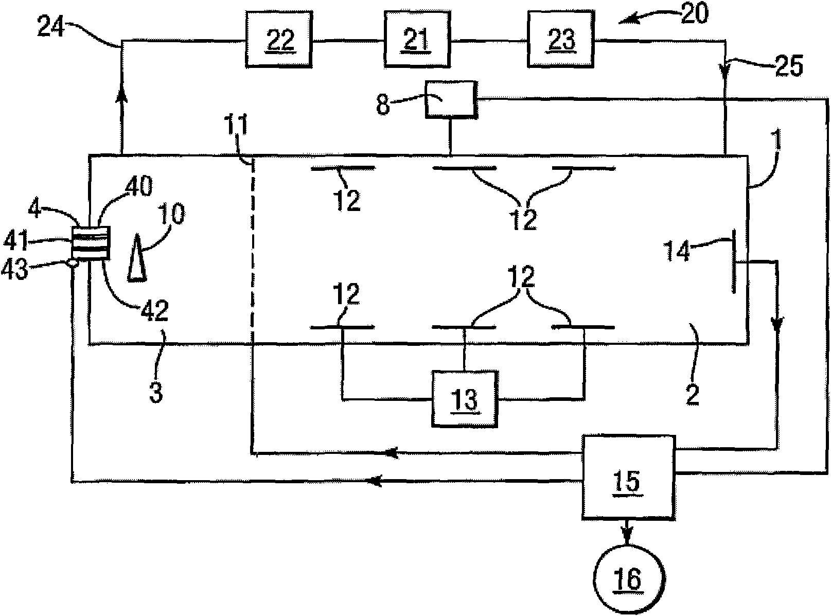
[0011] see first figure 1 , the apparatus takes the form of an ion mobility spectrometer (IMS) having a generally tubular housing 1 with a drift or analysis region 2 at its right-hand end and a reaction or ionization region 3 at its opposite left-hand end .

[0012] The inlet 4 at the left-hand end of the housing 1 communicates with the interior of the reaction zone 3, whereby molecules of interest can enter the reaction zone from the outside. Inlet 4 will be described in detail later.

[0013] The reaction zone 3 contains several means for ionizing the molecules of the analyte, such as high potential corona discharge points 10 . Both reaction zone 3 and drift zone 2 are at atmospheric pressure or only slightly below atmospheric pressure. The reaction region 3 and the drift region 2 are separated from each other by an optional conventional electrostatic shutter, such as a B. Nelson gate 11, which controls the flow of ions into the drift region. The drift region 2 has a ser...


PUM


Abstract

An IMS detector has a pin-hole or capillary inlet (4, 104, 204) having a coating (42, 242) of a material, such as polydimethylsiloxane, which is adsorbent to an analyte substance of interest. The analyte is adsorbed into the material (42, 242) until a heater (43) is energised to heat the material and release the adsorbed analyte substance for detection.

Description

technical field [0001] The present invention relates to a detector device having an inlet in the form of a pinhole or capillary channel through which analyte is allowed to enter the interior of the detector and to be supplied to a preconcentrator. Background technique [0002] Ion Mobility Spectrometry or IMS (Ion Mobility Spectroscopy) devices are often used to detect substances such as explosives, narcotics, corrosive and neurological agents. An IMS device generally includes a detector unit to which an air sample containing a suspect substance or analyte is continuously provided in the form of a gas or vapor. The cell operates at or near atmospheric pressure and contains electrodes to which voltage is applied to create a voltage gradient along the cell. Molecules in the air sample have been ionized (for example by means of a radioactive source, UV source or corona discharge) and are provided to the drift region in the cell by an electrostatic gate at one end. The ionized...

Claims


Application Information

Patent Timeline
Patent Type & Authority Applications(China)
IPC IPC(8): G01N27/64G01N1/40
CPCG01N27/622G01N1/405Y10T436/255G01N27/64G01N1/40
Inventor S·J·泰勒
Owner SMITHS DETECTION WATFORD LTD
Why Eureka
Try Eureka