Rolling pulley machine

A technology of pulley machine and pulley frame, which is applied in the direction of wheels, web-type wheels, transportation and packaging, etc., which can solve the problems of long casting time and achieve the effects of short manufacturing, high efficiency, stable and reliable quality

Inactive Publication Date: 2009-11-25
常州创联矿山设备制造有限公司
View PDF0 Cites 7 Cited by
  • Summary
  • Abstract
  • Description
  • Claims
  • Application Information

AI Technical Summary

Problems solved by technology

[0002] At present, pulleys are widely used, and the requirements for pulleys are becoming more and more stringent. The existing pulley manufacturing methods are mainly casting, riveting, welding, stamping, rolling and other methods, and then casting is the most commonly used method, but casting longer time

Method used


Image

  • Rolling pulley machine
  • Rolling pulley machine
  • Rolling pulley machine

Examples


Embodiment Construction

[0016] The present invention is described in further detail now in conjunction with accompanying drawing. These drawings are all simplified schematic diagrams, which only illustrate the basic structure of the present invention in a schematic manner, so they only show the configurations related to the present invention.

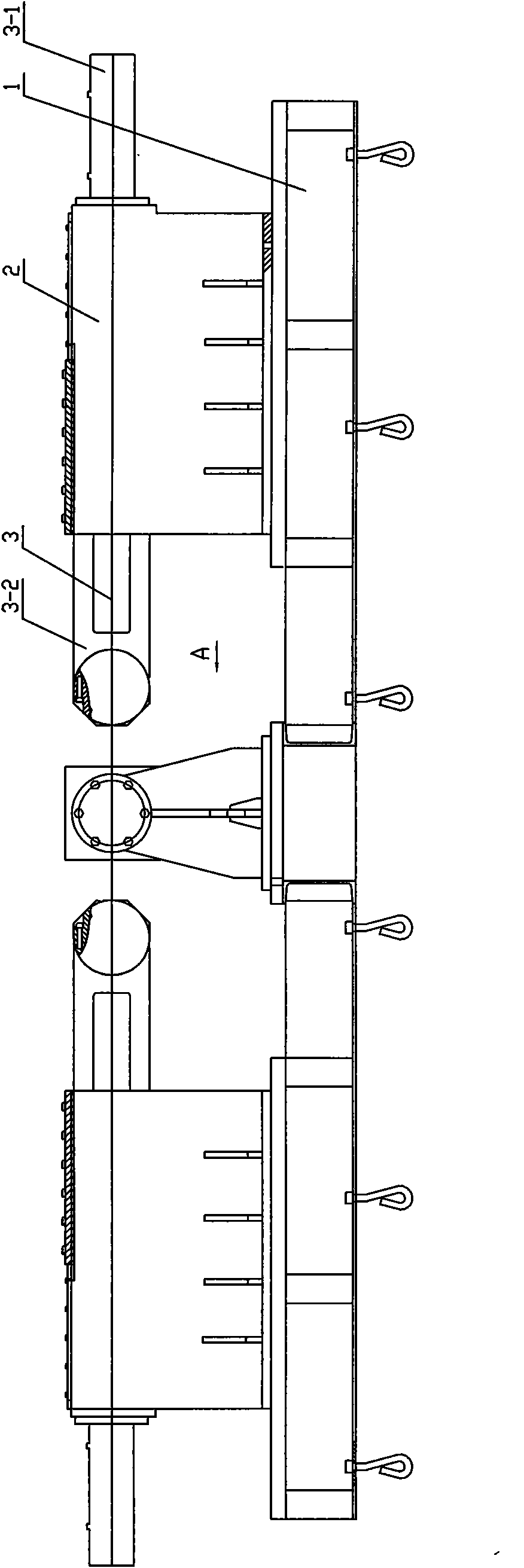
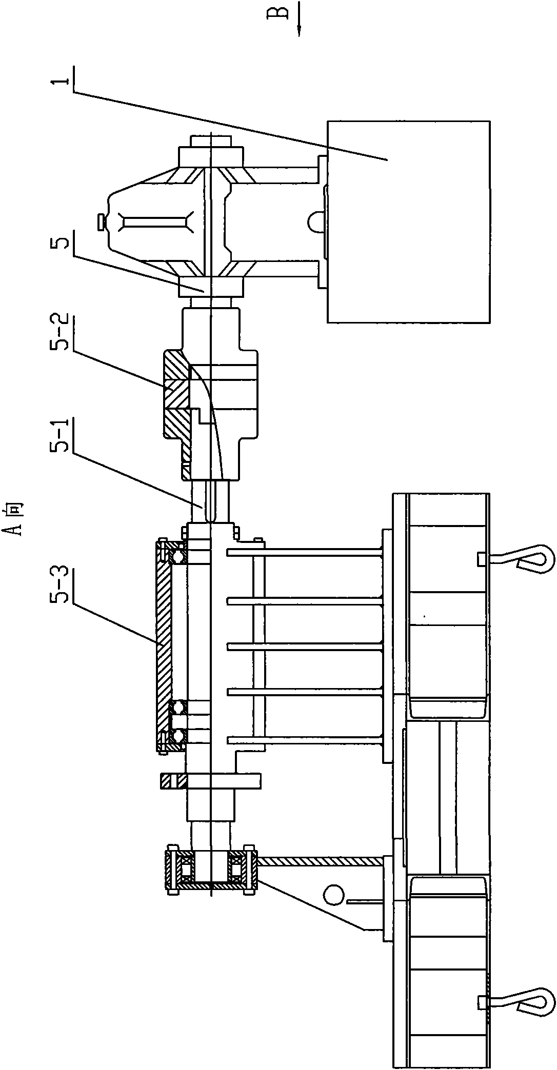
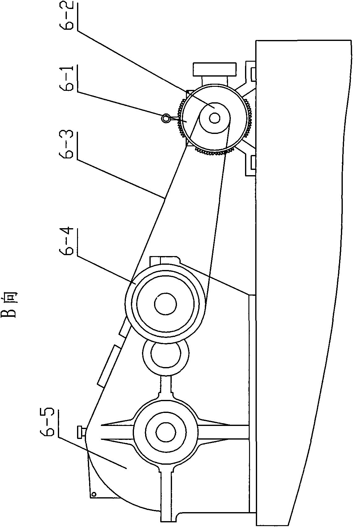
[0017] Such as figure 1 , figure 2 , image 3 The rolling pulley machine shown has a base 1, and a frame 2 is arranged on the base 1. Two horizontal slider assemblies 3 and a driving device 4 that drives the slider assembly 3 to move linearly are connected to the frame 2. On the base 1, The pulley frame 5 and the power unit 6 that are connected with fixed pulley. The driving device 4 includes a hydraulic cylinder 3-1, the pulley frame 5 includes a main shaft 5-1 connected to the pulley, a coupling 5-2 and a main engine 5-3 arranged on the main shaft 5-1, and the power unit 6 includes a power source motor 6 -1, the small pulley 6-2 connected with the motor...


PUM


Abstract

The invention relates to the pulley process equipment field, especially a rolling pulley machine with a base. A frame is arranged on the base. The frame is connected with two horizontal sliding pieces and a drive device driving the sliding piece to move straightly. A pulley fork for fixing the pulley and a power device are connected on the base. The drive device comprises a hydraulic cylinder. The pulley yoke comprises a main shaft connected with the pulley, a coupling and a mainframe on the main shaft. The power device comprises a power source motor, a small belt pulley connected with the motor, a large belt pulley connected with the small belt pulley through the belt and a speed reducer connected with the large belt pulley. The sliding piece comprises a sliding piece bearing seat arranged on the frame and a sliding piece matrix connected with the sliding piece bearing seat. The invention has the advantages of reasonable integral structure, high strength, light weight, long service life and reliable quality.

Description

technical field [0001] The invention relates to the field of pulley processing equipment, in particular to a rolling pulley machine. Background technique [0002] At present, pulleys are widely used, and the requirements for pulleys are becoming more and more stringent. The existing pulley manufacturing methods are mainly casting, riveting, welding, stamping, rolling and other methods, and then casting is the most commonly used method, but casting A long time. Contents of the invention [0003] The technical problem to be solved by the present invention is to provide a rolling pulley machine in order to solve the above-mentioned shortcomings and deficiencies. [0004] The technical solution adopted by the present invention to solve the technical problem is: a rolling pulley machine with a base, a frame is arranged on the base, two horizontal sliders and a driving device for driving the sliders to move linearly are connected to the frame, The base is connected with a pull...

Claims


Application Information

Patent Timeline
Patent Type & Authority Applications(China)
IPC IPC(8): B21H1/02
Inventor 王晓春
Owner 常州创联矿山设备制造有限公司
Why Eureka
Try Eureka