
Rotary piston engine

A technology of rotating pistons and engines, which is applied in the direction of internal combustion piston engines, combustion engines, machines/engines, etc., and can solve problems such as complex structures, reciprocating inertial forces and moments of inertia that cannot be completely balanced, and unfavorable fuel combustion and diffusion.

Inactive Publication Date: 2009-11-25
卢能才
View PDF0 Cites 2 Cited by
  • Summary
  • Abstract
  • Description
  • Claims
  • Application Information

AI Technical Summary

Problems solved by technology

The main disadvantages of this engine are 1. Complex structure, large volume and heavy weight
2. The reciprocating inertial force and moment of inertia caused by the reciprocating motion of the piston in the crank-connecting rod mechanism cannot be completely balanced. The magnitude of this inertial force is proportional to the square of the speed, which reduces the smoothness of the engine's operation and limits the development of high-speed engines.
3. Since the working method of the four-stroke reciprocating piston engine is that three of the four strokes completely rely on the inertial rotation of the flywheel, resulting in very uneven power and torque output of the engine, although modern engines use multi-cylinder and V-shaped arrangements. reduce this shortcoming, but it is impossible to eliminate it completely
However, because the combustion chamber of this engine is not very conducive to the combustion and diffusion of fuel, the fuel consumption rate is high and the exhaust emissions are more pollutants. For diesel engines, this severely limits the popularization and application of the rotary engine

Method used


Image

  • Rotary piston engine
  • Rotary piston engine
  • Rotary piston engine

Examples


Embodiment Construction

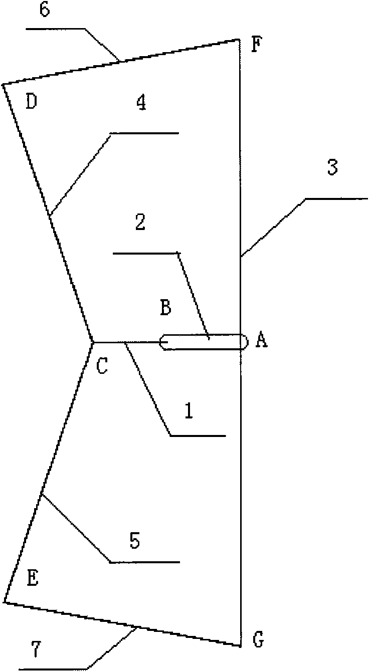
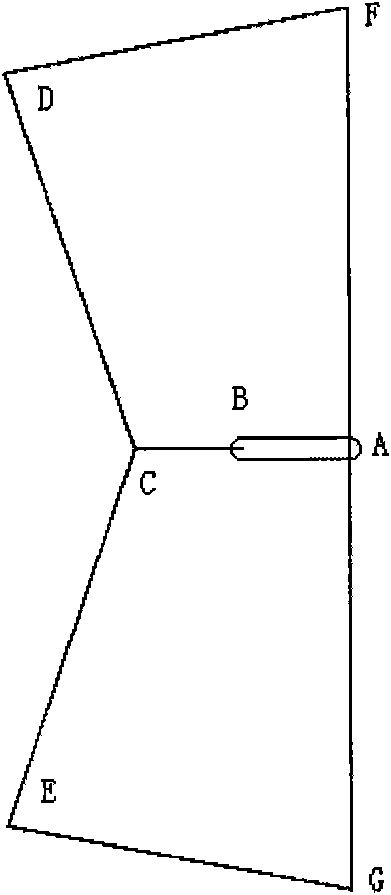
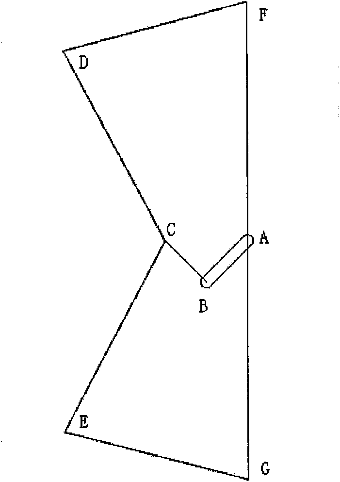
[0031]As shown in Figure 1, draw a simplified structural diagram of the engine. If the output shaft 1 rotates around point C relative to the fixed cylinder, the internal eccentric shaft 2 rotates around point B relative to the output shaft 1, and the rotor 3 rotates around point A. Since the rotational speed ratio of the inner eccentric shaft 2 is 1:-2:1, and the eccentricity of the output shaft, namely the BC length, is equal to the eccentricity of the inner eccentric shaft, namely the AB length, then point A will always move back and forth on a horizontal line segment, The length from the two ends of the line segment to point C is AB+BC. Since the rotating speed of the rotor relative to the fixed cylinder is zero, the two ends F and G on the rotor move similarly to point C, and they all move back and forth on a line segment. The length of the connecting rod 6 is DF, the length of the connecting rod 7 is EG, the length of the push rod 4 is DC, and the length of the push rod 5...


PUM


Abstract

The invention relates to an engine, in particular to a rotary piston engine which comprises one or two annular air cylinders, wherein each annular air cylinder is correspondingly provided with two rotators which are respectively provided with a plurality of pistons; the two groups of the pistons are arranged in the air cylinder at intervals and divide the air cylinder into a plurality of work rooms with variable volumes; a drive shaft of the engine adopts a double eccentric mechanism and comprises an inner eccentric shaft (2) and an output shaft (1), and the inner eccentric shaft is arranged in an eccentric hole of the output shaft; a rotor (3) is arranged on an eccentric shaft neck of the inner eccentric shaft, and both ends of the rotor are respectively connected with the two rotators in each air cylinder in a controllable mode through two connecting rods (6) and (7) and two crank arms (4) and (5); if both ends of the rotor, the inner eccentric shaft and the output shaft are rotated at a uniform speed, the two crank arms and each rotator are rotated at a rotating speed of cyclical fluctuation; and after the rotor is rotated for one circle, the rotators are respectively rotated for one circle.

Description

Technical field: [0001] This patent relates to an engine, especially a rotary piston engine. Background technique: [0002] The traditional four-stroke piston reciprocating engine relies on the combustion of fuel in the combustion chamber to push the piston to reciprocate up and down or horizontally, and then convert the linear motion of the piston into the rotation of the crankshaft through the connecting rod and crankshaft. The main disadvantages of this engine are 1. The structure is complex, bulky and heavy. 2. The reciprocating inertial force and moment of inertia caused by the reciprocating motion of the piston in the crank-connecting rod mechanism cannot be completely balanced. The magnitude of this inertial force is proportional to the square of the speed, which reduces the smoothness of the engine's operation and limits the development of high-speed engines. 3. Since the working method of the four-stroke reciprocating piston engine is that three of the four strokes...

Claims


Application Information

Patent Timeline
Patent Type & Authority Applications(China)
IPC IPC(8): F02B53/00F02B55/02
CPCY02T10/17Y02T10/12
Inventor 卢能才
Owner 卢能才
Learn More