Oversize self-aligning roller bearing

A self-aligning roller bearing, super-large technology, applied in the field of bearings, can solve problems such as deviation of the center diameter of the pocket, easy deformation of the cage, and increase in the rated load of the bearing, so as to meet the requirements of reducing assembly accuracy, reduce manufacturing costs, and improve Effect of rated load

Inactive Publication Date: 2009-11-25
瓦房店第一轧机轴承制造有限公司
View PDF0 Cites 4 Cited by
  • Summary
  • Abstract
  • Description
  • Claims
  • Application Information

AI Technical Summary

Problems solved by technology

[0003] 1. The beam between the two pockets of the comb-shaped cage of the existing structure must have a certain width to meet the strength requirements of the cage, which limits the increase in the number of rollers and the increase in the rated load of the bearing
[0004] 2. The pockets of the comb-shaped cage of the existing structure must have a certain containment capacity, otherwise the rollers will easily fall off, which requires that the outer diameter of the cage should not be too small, but it should not be too large, otherwise the bearing assembly will be difficult. This increases the difficulty of wide series bearing design
[0005] 3. For the comb-shaped cage of the existing structure, due to the machining error of the pocket diameter, the roller also has a machining error. Although the errors of both are very small and within the control range, the smallest pocket and the roller may appear during assembly. In the maximum case, part of the gap is eaten, and the cage is easily deformed during the pocket hole processing, resulting in a deviation in the center diameter of the pocket hole. These phenomena will easily cause the rotation of the bearing to be inflexible after assembly.
[0006] 4. Due to the relatively large size of the comb-shaped cage of the super-large bearing, the cost of the work card measuring tool is also relatively high

Method used


Image

  • Oversize self-aligning roller bearing
  • Oversize self-aligning roller bearing
  • Oversize self-aligning roller bearing

Examples


Embodiment Construction

[0014] The specific implementation manner of the present invention will be further described below in conjunction with the accompanying drawings.

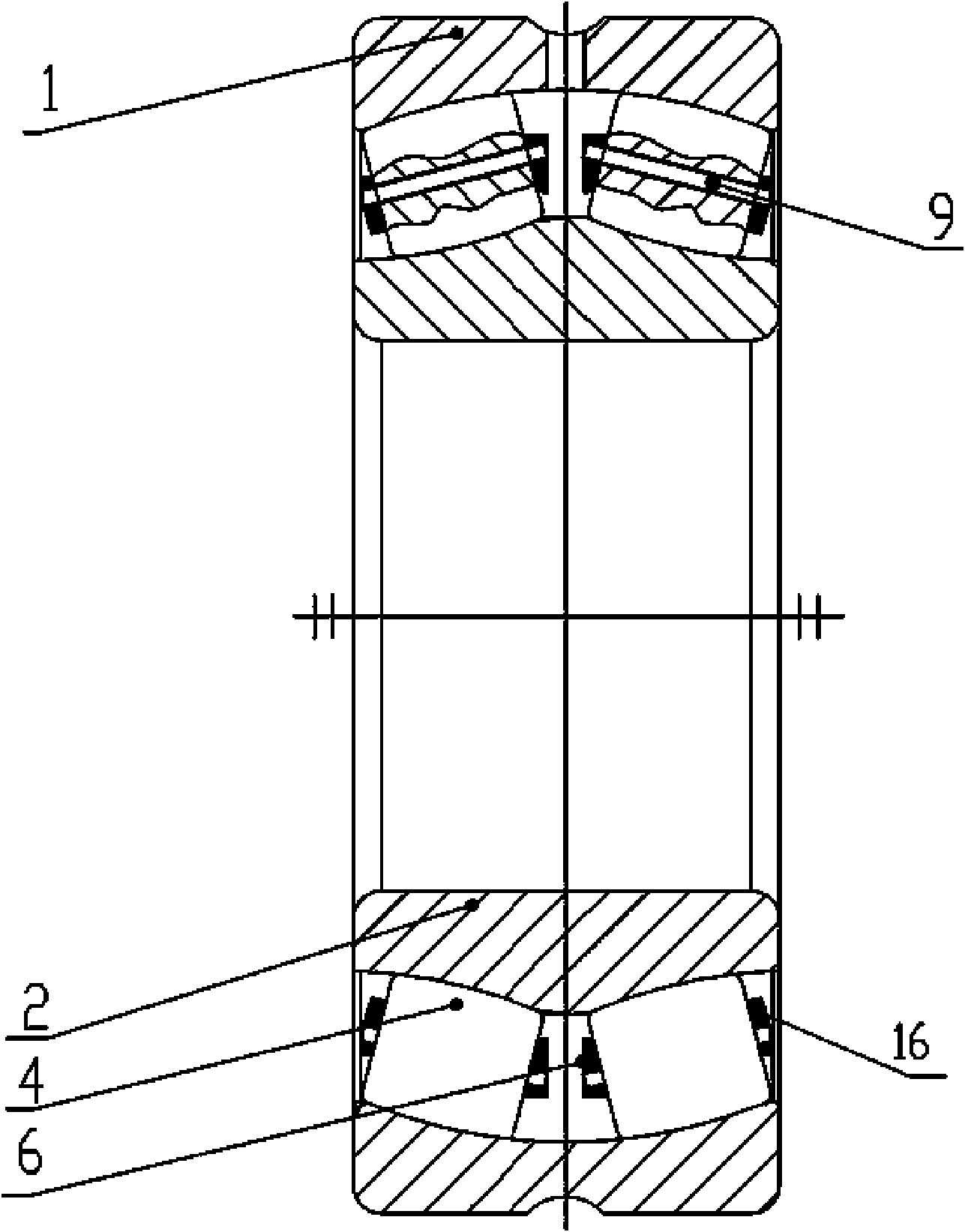
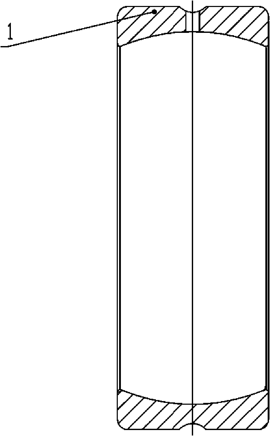
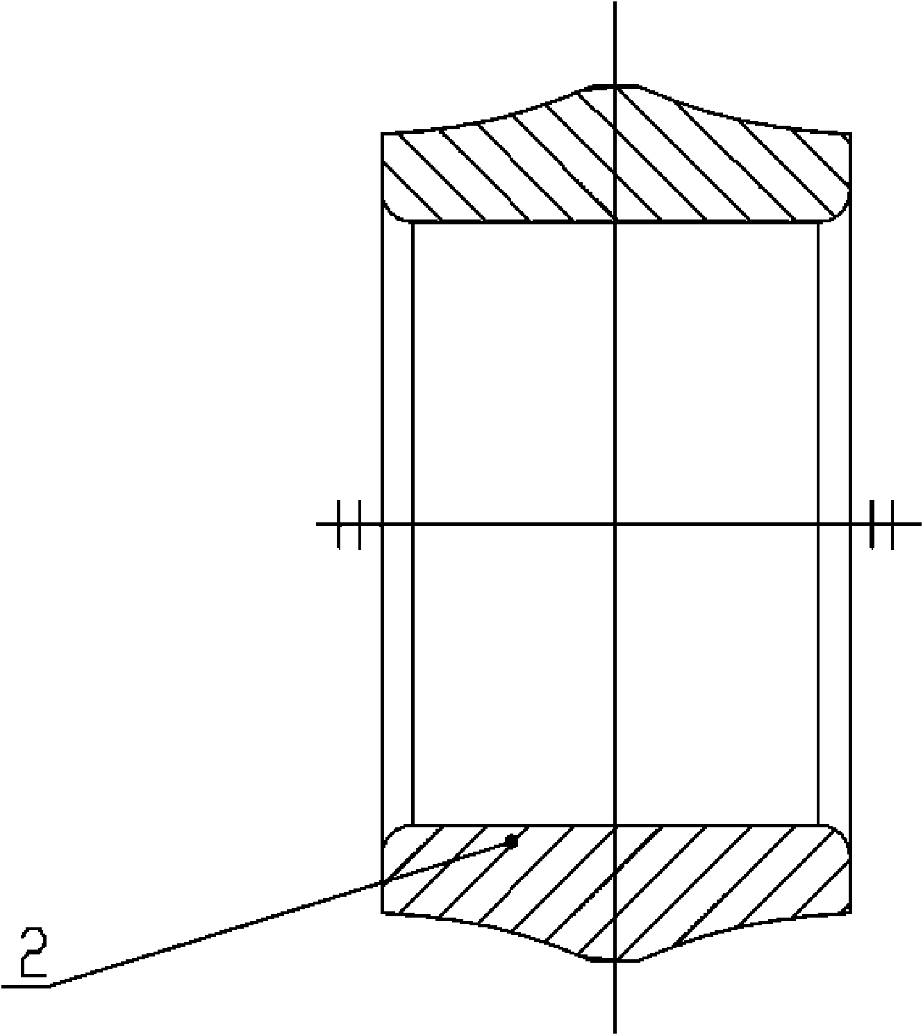
[0015] Such as Figure 1~3 As shown, a super large spherical roller bearing is provided with an outer ring 1 and an inner ring 2. The outer ring 1 has an inner spherical raceway, and the inner ring 2 has no middle and small ribs. There is a cage between the two inner rings, and two sets of spherical rollers 4 are installed in the cage. A through hole is opened in the center of rotation of each spherical roller 4. The cage is composed of a pin shaft 9 and a pin shaft 9 The inner plate-shaped annular cage 6 and the outer plate-shaped annular cage 16 are formed at both ends, wherein the pin shaft 9 runs through the through hole at the center of rotation of the spherical roller 4, and the inner and outer plate-shaped annular cages are placed on the spherical roller 4 both ends. Each set of bearings has four plate-shaped annular cages...


PUM


Abstract

The invention discloses an oversize self-aligning roller bearing, which is provided with an outer ring (1) and an inner ring (2). A retainer is arranged between the outer ring (1) and the inner ring (2), and two groups of spherical rollers (4) are arranged in the retainer. The oversize self-aligning roller bearing is characterized in that: the rotation center of each spherical roller (4) is provided with a through hole; and the retainer consists of a pin shaft (9), and an inner plate annular retainer (6) and an outer plate annular retainer (16) at two ends of the pin shaft (9), wherein the pin shaft (9) runs through the through hole at the rotation center of the spherical roller (4), and the inner plate annular retainer and the outer plate annular retainer are arranged at two end faces of the spherical roller (4). The retainer is not integrated, but assembled, so the requirement of assembly precision between the retainer and the spherical rollers is reduced, and the retainer is easy to process and reduces the manufacturing cost. Moreover, the bearing can increase the number of the rollers as much as possible, and improves the rated load.

Description

Technical field: [0001] The invention relates to a bearing, in particular to a super large self-aligning roller bearing with a new structure. Background technique: [0002] As a commonly used standard part, bearings have been widely used in various mechanical fields, but there are the following problems in the existing structure of wide series super large bearings: [0003] 1. The beam between the two pockets of the comb-shaped cage of the existing structure must have a certain width to meet the strength requirements of the cage, which limits the increase in the number of rollers and the increase in the rated load of the bearing. [0004] 2. The pockets of the comb-shaped cage of the existing structure must have a certain containment capacity, otherwise the rollers will easily fall off, which requires that the outer diameter of the cage should not be too small, but it should not be too large, otherwise the bearing assembly will be difficult. This increases the difficulty of...

Claims


Application Information

Patent Timeline
Patent Type & Authority Applications(China)
IPC IPC(8): F16C23/08F16C33/36F16C33/50
Inventor 宋海芳陶永刚胡伟海宋伯仁杜以月
Owner 瓦房店第一轧机轴承制造有限公司
Why Eureka
Try Eureka