Optical glass optical homogeneity test device and test method

A technology of optical uniformity and testing device, applied in the direction of testing optical performance, etc., can solve the problems of high cost, expensive interferometer, low accuracy of interferometer, etc., and achieve the effects of low cost, convenient testing method and simple device

Active Publication Date: 2009-11-25
CDGM OPTICAL GLASS
View PDF0 Cites 14 Cited by
  • Summary
  • Abstract
  • Description
  • Claims
  • Application Information

AI Technical Summary

Problems solved by technology

This method is often used in small-aperture interferometers. When used on large-aperture interferometers, the cost will become very high, and the accuracy of the interferometer with piezoelectric ceramic devices is lower than that without piezoelectric ceramics; Another method is to use...

Method used


Image

  • Optical glass optical homogeneity test device and test method
  • Optical glass optical homogeneity test device and test method
  • Optical glass optical homogeneity test device and test method

Examples


Embodiment Construction

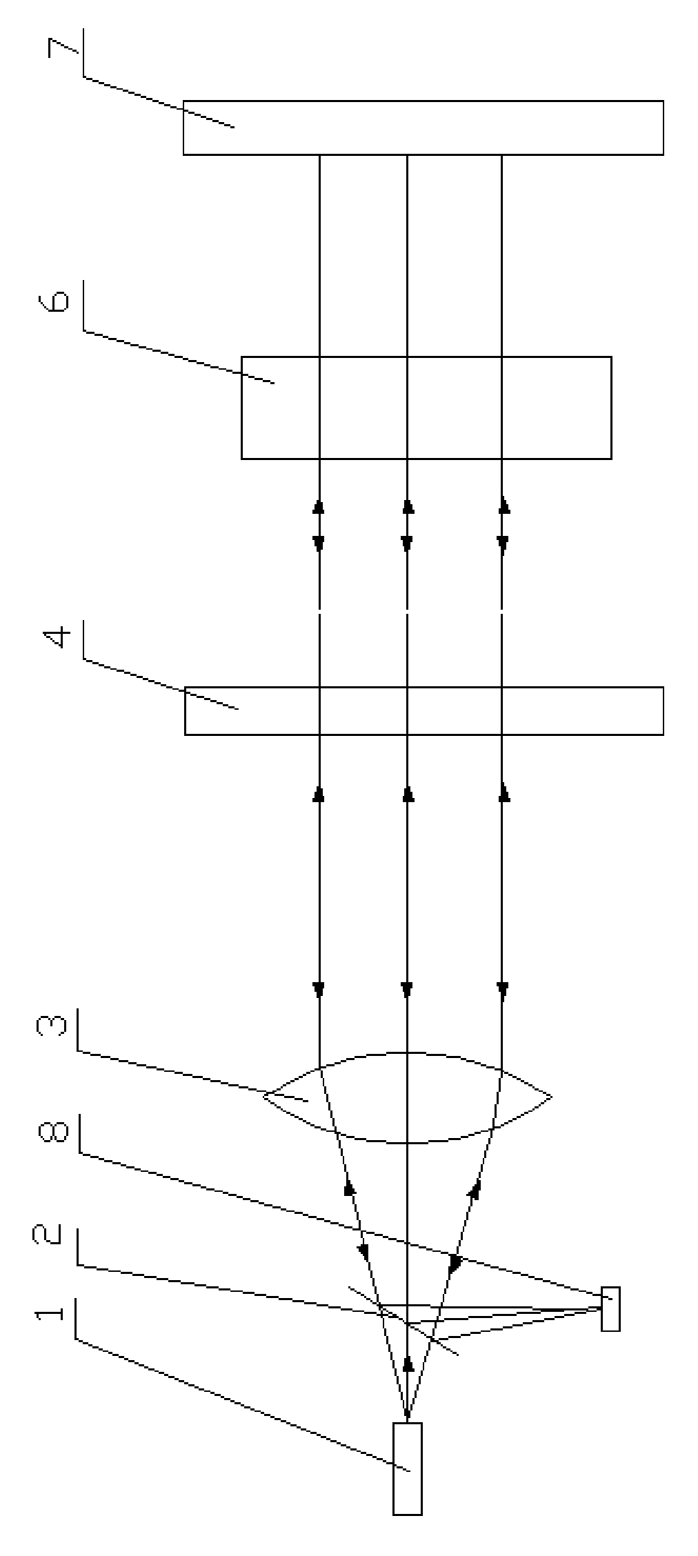
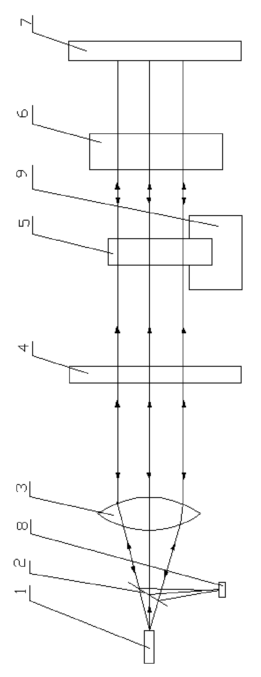
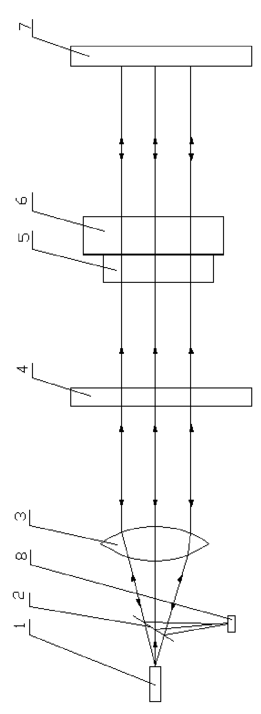
[0019] Such as figure 2 As shown, the device of the present invention is to increase and place a direction discrimination standard sample 5 between the lens 4 and the reflector 7 on the existing Fizeau interferometer, and one side of the direction discrimination standard sample 5 is made into a standard plane, and the other side Make a surface with a POWER value, and the PV values ​​in each direction are equal, along the direction of the light path, the surface with the POWER value of the direction discrimination standard sample 5 is in front, and the standard plane is behind, so that when the plane light wave passes through the direction discrimination standard sample 5 , will form an almost standard spherical wave.

[0020] The direction judging standard sample 5 can be used to judge the direction of light wave distortion in the optical uniformity test. The direction discrimination standard sample 5 is made of quartz glass, because the stability of quartz glass is better a...


PUM


Abstract

The invention provides a device capable of judging the optical wave deformation direction in an optical homogeneity test with low cost. The optical glass optical homogeneity test device comprises a Fizeau interferometer. A direction determining standard sample is disposed between a beam splitter and a reflector on the Fizeau interferometer. The invention directly arranges the direction determining standard sample between the beam splitter and the reflector on the Fizeau interferometer. The device has the advantages of simple structure, convenient maintenance, low cost and convenient test method and is in particular suitable to test of the large optical glass.

Description

technical field [0001] The invention relates to an optical glass optical uniformity testing device and a method thereof, in particular to an optical glass optical uniformity testing device and a method thereof capable of judging the direction of light wave distortion. Background technique [0002] The optical uniformity of glass is an important indicator of the quality of optical glass. At present, the most commonly used test method is to use Fizeau (Fizeau) interferometer to measure, such as figure 1 As shown, the Fizeau interferometer is composed of He-Ne laser 1, semi-reflective and semi-transparent plate 2, beam expander system 3, mirror 4, mirror 7 and CCD8, and the coherent light emitted by the He-Ne laser passes through the semi-reflective The semi-transparent plate 2 and the beam expander system 3 are expanded, and the light is divided into two parts at the mirror 4, and one part returns along the original path. This part is the reference light, and the wave surface ...

Claims


Application Information

Patent Timeline
IPC IPC(8): G01M11/02
Inventor 毛露路胡熔田丰贵吴志强许国珍张晓刚
Owner CDGM OPTICAL GLASS
Why Eureka
Try Eureka