Self-adapting real-time regulating method for linear array remote sensing CCD camera dynamic range

A dynamic range and real-time adjustment technology, which is applied to TV, color TV parts, electrical components, etc., can solve the problems of adjusting dynamic range and a large number of stripes in images, and achieves the effect of ensuring accuracy, simple method, and improving exposure time

Active Publication Date: 2009-11-25
BEIJING RES INST OF SPATIAL MECHANICAL & ELECTRICAL TECH
View PDF0 Cites 35 Cited by
  • Summary
  • Abstract
  • Description
  • Claims
  • Application Information

AI Technical Summary

Problems solved by technology

The linear array CCD is imaging by row, there is no concept of frame, and the linear array CCD needs the swing of the camera to dynamically image, and each imaging moment can only form a single row of pixels, so the method of adjusting the dynamic range cannot be adjusted according to the area array CCD To adjust the dynamic range as a whole, if the dynamic range adjustment method of the area array CCD camera is used, there will be a lot of stripes in the image after the dynamic range adjustment of the line array CCD camera, so the line array CCD camera must use a completely different method to adjust the dynamic range

Method used


Image

  • Self-adapting real-time regulating method for linear array remote sensing CCD camera dynamic range
  • Self-adapting real-time regulating method for linear array remote sensing CCD camera dynamic range
  • Self-adapting real-time regulating method for linear array remote sensing CCD camera dynamic range

Examples


Embodiment Construction

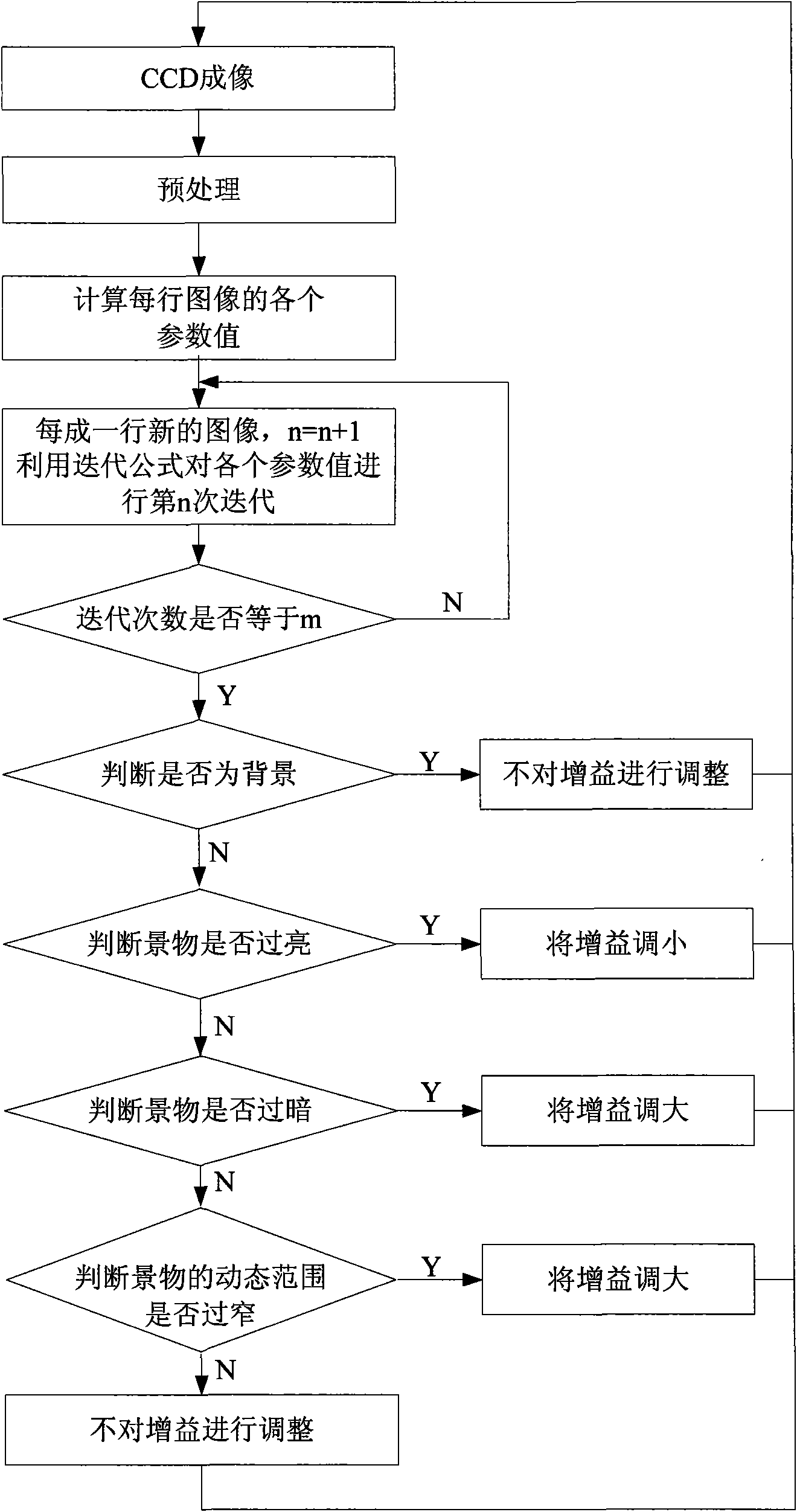
[0028] Such as figure 1 As shown, the steps of the linear array remote sensing CCD camera dynamic range adaptive real-time adjustment method of the present invention are as follows:

[0029] 1. Receive image data line by line from the linear array remote sensing CCD camera, and remove noise points contained in each line of image data.

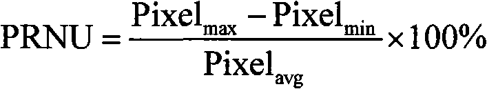
[0030] Various noises will be generated during the CCD imaging process, mainly including fixed pattern noise, random noise, shot noise, readout noise, etc. Usually, the signal-to-noise ratio of the system is about 48dB, and the noise of the system (including random noise, shot noise, Readout noise, etc.) is about 1 DN value (8-bit quantization), and the fixed pattern noise of CCD is generally less than 3%. According to the fixed pattern noise calculation formula:

[0031] PRNU = Pixel max - Pixel min ...


PUM


Abstract

A self-adapting real-time regulating method for the linear array remote sensing CCD camera dynamic range, includes the steps: (1)setting the statistical property values of the image data; (2)receiving the image data line by line and removing the noise spot; (3)predicting for the next line of image data by utilizing a attenuation factor; (4)calculating each statistical property value of the predicted image data; (5) if the calculated variance being smaller than the variance threshold value, keeping the linear array CCD integral time constant, otherwise, (6)if the calculated average value being more than the average value upper limit value, decreasing the linear array CCD integral time; if the average value being smaller than the average value lower limit value, increasing the linear array CCD integral time; if the average value being between the average value upper limit value and the average value lower limit value, transferring the step (7), (7) if the difference of the calculated grey scale maximum value to the calculated grey scale minimal value being smaller than the grey scale threshold value, increasing the linear array CCD integral time, otherwise keeping the linear array integral time constant. The method of the invention has high modulation accuracy and good real time, and is beneficial for the realization on the present remote sensing linear array CCD camera.

Description

technical field [0001] The invention relates to a method for adjusting the dynamic range of a camera, in particular to a method for adaptively adjusting the dynamic range of a linear array CCD camera for satellites. Background technique [0002] Dynamic range is an important performance index of remote sensor. Whether its design is reasonable or not is directly related to the level, brightness and contrast of satellite images, and ultimately affects the image quality. If the design of the dynamic range is unreasonable, it will cause high-end saturation in the image, loss of information or high-end idle, information compression at the low end, etc. [0003] Through tracking, statistics and analysis of remote sensing satellite image quality, it is found that it has the following characteristics: First, in the same orbit satellite image, under the same camera parameter settings, the brightness of satellite images in different regions varies greatly. Some images have very rich ...

Claims


Application Information

Patent Timeline
Patent Type & Authority Applications(China)
IPC IPC(8): H04N17/00H04N5/225
Inventor 王琨陈彦李涛彭妮娜
Owner BEIJING RES INST OF SPATIAL MECHANICAL & ELECTRICAL TECH
Why Eureka
Try Eureka