Thread clamping device of sock machine

A thread clamping and hosiery machine technology, which is applied in textiles and papermaking, weft knitting, knitting, etc., can solve the problems of increasing labor intensity, reducing labor intensity, and high cost, so as to improve the quality of socks, reduce labor intensity, and reduce manufacturing cost effect

Inactive Publication Date: 2009-12-02
吴新军
View PDF1 Cites 12 Cited by
  • Summary
  • Abstract
  • Description
  • Claims
  • Application Information

AI Technical Summary

Problems solved by technology

[0004] The invention mainly solves the problem that the thread clamping device on the hosiery machine's half plate cannot clamp the naked spandex yarn with a very thin wire diameter, high elasticity and smooth surface, resulting in yarn running phenomenon during production, which affects the quality of socks and increases labor costs. The technical problem of strength; provide a sock clamping device that can clamp naked spandex yarn well, so that there will be no yarn running phenomenon in production, reduce labor intensity, and ensure the quality of socks
[0005] The invention also solves the technical problem that the original sock clamping device cannot clamp naked spandex yarn, so that socks can only be woven with spandex-wrapped yarn, resulting in inferior quality, appearance and comfort of socks, and high cost; Provide a sock thread clamping device that can effectively clamp naked spandex yarn, so that socks can be directly woven with naked spandex yarn, thereby improving the quality, appearance and comfort of socks, and reducing costs

Method used


Image

  • Thread clamping device of sock machine
  • Thread clamping device of sock machine
  • Thread clamping device of sock machine

Examples


Embodiment 1

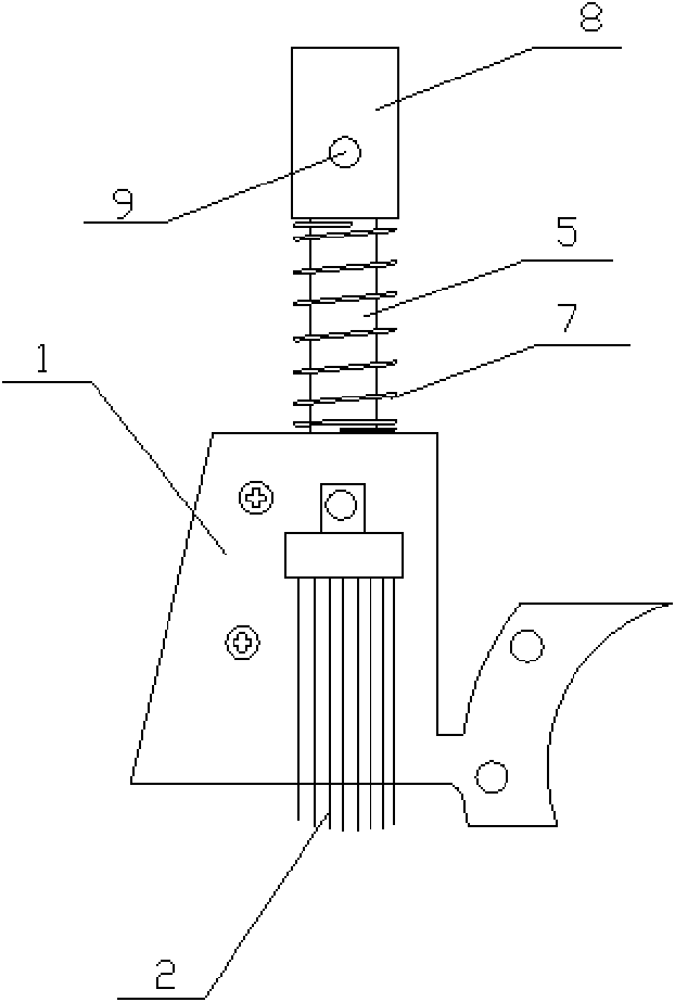
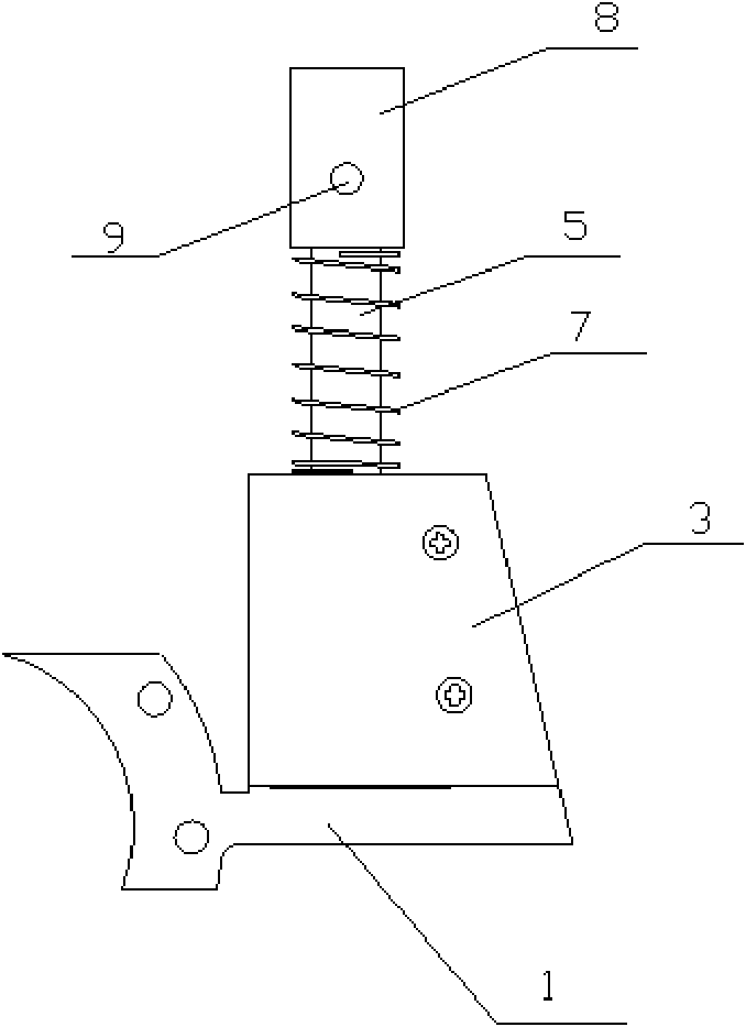
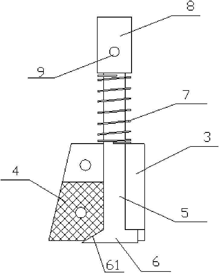
[0025] Embodiment 1: The hosiery machine clamping device of this embodiment, such as figure 1 , figure 2 , image 3 , Figure 6 As shown, it includes a brush holder 1 and a brush 2 installed on the brush holder 1. The back of the brush holder 1 is connected with a clamping cover 3 by bolts, and the clamping cover 3 and the brush holder 1 are surrounded by The cavity is installed with an elastic clamping piece 4 and a clamping rod 5 that can be raised or lowered. The bottom end of the clamping rod 5 has a clamping head 6. The clamping rod 5 and the clamping head 6 are integrally made. The top of the clamping rod 5 Stretch out the clamping cover plate 3 and the brush holder 1, the top of the clamping rod 5 is connected with the clamping rod fixing head 8, and the top of the clamping rod 5 extends into the clamping rod from the bottom of the clamping rod fixing head 8 to fix In the head 8, the two are connected together by bolts 9, and the spring 7 is set on the clamping rod ...


PUM


Abstract

The invention relates to a thread clamping device of a sock machine. The front side of a brush rack is provided with a brush; the back side of the brush rack is provided with a thread camping cover plate; a cavity enclosed by the thread camping cover plate and the brush rack is internally provided with an elastic thread clamping piece and a thread clamping rod capable of ascending or descending; the bottom end of the thread clamping rod is provided with a thread clamping end; the thread clamping side of the threading clamping end and the thread clamping side of the elastic thread clamping piece can be jointed or separated; the top end of the thread clamping rod extends out of the thread clamping cover plate and the brush rack, and stretches into a fixing end of the thread clamping rod from the bottom part of the fixing end of the thread clamping rod; the top end of the thread clamping rod is connected with the fixing end of the thread clamping rod through a bolt; and the thread clamping rod positioned between the fixing end of the thread clamping rod and the thread clamping cover plate is sleeved with a spring. The device controls the separation or joint of the thread clamping side of the thread clamping end and the thread clamping piece of the elastic thread clamping piece through an air cylinder of the sock machine, and naked spandex silk is effectively clamped during fitting, so that the phenomenon of yarn running cannot occur. The device reduces the labor intensity, makes full use of naked spandex silk in hosiery, improves the sock quality and reduces the sock manufacturing cost.

Description

technical field [0001] The invention belongs to the field of knitting machinery manufacturing, and in particular relates to a hosiery machine thread clamping device which can well clamp naked spandex yarns during hosiery knitting. Background technique [0002] The thread clamping device on the half disk on the existing hosiery machine is the brush installed on the brush frame, which can only clamp the thread material formed by covering the naked spandex yarn outside the yarn, that is, the spandex covered yarn. , the spandex-wrapped yarn used for hosiery is guided and clamped by the brush. When working, the spandex-wrapped yarn is pulled by the half disc scissors to pass through the brush. When the spandex-wrapped yarn is drawn to the position of the small scissors, the small scissors cooperate with the disc scissors to cut the yarn. At this time, the brush Hold down the yarn and keep it still, so that it is convenient for the half disc scissors to hook the thread when weavi...

Claims


Application Information

Patent Timeline
Patent Type & Authority Applications(China)
IPC IPC(8): D04B15/60
Inventor 吴新军
Owner 吴新军
Why Eureka
Try Eureka