Hydraulic auto-tensioner with double seal ring

A tensioner, hydraulic technology, applied in the direction of transmission, valve drive, engine components, etc., can solve the scratches and streaks in the plunger and housing plunger hole, automatic tensioner efficiency and performance characteristics , high cost of structural design and other issues, to achieve the effect of reducing the tendency of leakage, reducing the tendency of bonding, and improving the guiding characteristics

Inactive Publication Date: 2009-12-02
IWIS MOTORSYSTEME GMBH & CO KG
View PDF1 Cites 8 Cited by
  • Summary
  • Abstract
  • Description
  • Claims
  • Application Information

AI Technical Summary

Problems solved by technology

However, even very small tilting movements of the tensioning plunger can cause scratches and streaks on the sliding surfaces of the plunger and housing plunger bore, which can negatively affect the efficiency and performance characteristics of this automatic tensioner Impact
In addition to the above-mentioned problems, the necessary good sealing of the relevant sliding seals needs to be paid attention to during the production of the free piston, which leads to high costs for the structural design and production of the free piston

Method used


Image

  • Hydraulic auto-tensioner with double seal ring
  • Hydraulic auto-tensioner with double seal ring
  • Hydraulic auto-tensioner with double seal ring

Examples


Embodiment Construction

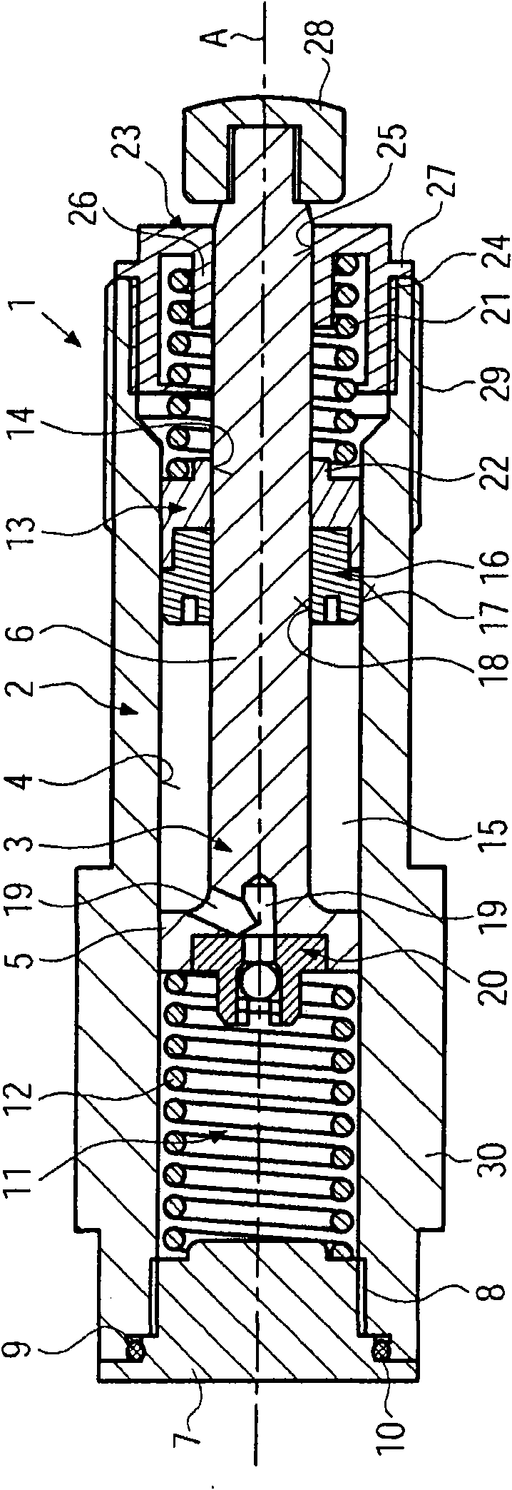
[0022] figure 1 A hydraulic self-contained automatic tensioner 1 is shown for a timing chain drive or an auxiliary unit drive of an internal combustion engine, the tensioner 1 comprising a hollow cylindrical housing 2 in which a tensioning plunger 3 is held The guidance is such that it is longitudinally displaceable along the axis A in the plunger bore 4 of the housing. The tensioning plunger 3 comprises a plunger bottom 5 through which the tensioning plunger 3 is guided in the plunger hole 4 and the plunger rod 6 follows said plunger bottom 5 across in the direction of tensioning and extension. At the end face of the housing 2 on the tensioning side of the hydraulic tensioner 1 , a pretensioning can be applied to the adjoining chain drive. On the installation side of the hydraulic tensioner 1, that is, on the side facing away from the tensioning side, an end plug 7 is arranged in an opening on the end face of the hollow cylindrical shell 2, and the end plug 7 passes through ...


PUM

PropertyMeasurementUnit
Axial lengthaaaaaaaaaa

Abstract

The present invention relates to a hydraulic auto-tensioner, in particular for a chain drive of an internal combustion engine, comprising a housing, a tensioning plunger guided in a plunger bore of said housing, a free piston guided in said plunger bore, and a plunger rod formed on said tensioning plunger and extending through the free piston. The tensioning plunger, the housing and the free piston delimit a hydraulic reservoir which is sealed with respect to the housing and the plunger rod by means of a sealing unit that is arranged on the free piston. The sealing unit is implemented as a double seal ring with an outer sealing surface which is in sliding contact with the plunger bore of the housing, and an inner sealing surface which is in sliding contact with the plunger rod of the tensioning plunger. In addition, the present invention relates to the use of such a double seal ring in a hydraulic auto-tensioner.

Description

technical field [0001] The invention relates to a hydraulic self-contained automatic tensioner, in particular for a chain drive of an internal combustion engine, comprising a housing, a tensioning column guided in a plunger bore of the housing a plug, a free piston guided in said plunger bore, a plunger rod formed on said tensioning plunger and extending through the free piston, a hydraulic reservoir defined by the tensioning plunger, housing and free piston, And a sealing unit arranged on the free piston sealing the hydraulic reservoir relative to the housing and the plunger rod. Background technique [0002] Simple tensioning devices, usually used as chain tensioners in timing chain drives of internal combustion engines, generally comprise a housing with a tensioning plunger arranged in the housing and pretensioned by a compression spring. A pressure chamber is formed between the tensioning plunger and the housing. The pressure chamber is filled with hydraulic medium for ...

Claims


Application Information

Patent Timeline
IPC IPC(8): F02B67/06F16H7/08
CPCF01L1/022F16H2007/0859F16H7/0836F16H2007/0806F01L1/02
Inventor A·邦加德O·道布
Owner IWIS MOTORSYSTEME GMBH & CO KG
Why Eureka
Try Eureka