
Film for flow valve

A flow valve and diaphragm technology, which is applied to the parts, valve details, and control valves in contact between the valve element and the valve seat.

Active Publication Date: 2019-09-10
ROBERT BOSCH GMBH
View PDF5 Cites 0 Cited by
  • Summary
  • Abstract
  • Description
  • Claims
  • Application Information

AI Technical Summary

Problems solved by technology

However, the anti-stick effect of the membrane can gradually deteriorate over time

Method used


Image

  • Film for flow valve
  • Film for flow valve
  • Film for flow valve

Examples


Embodiment Construction

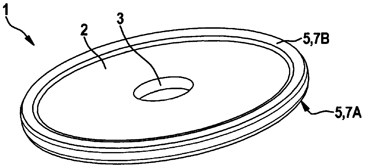
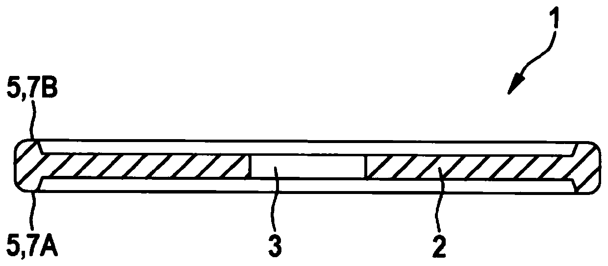
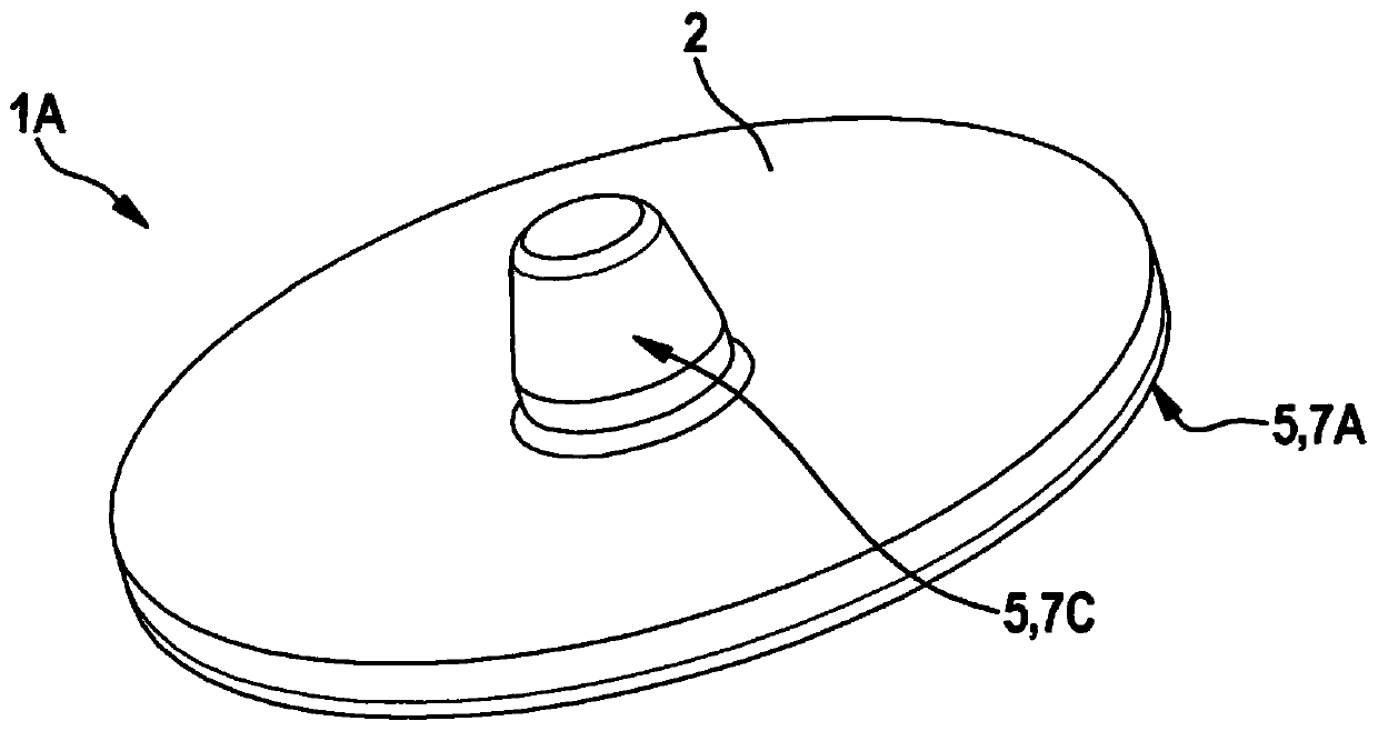
[0020] as by Figure 1 to Figure 5 As can be seen, in the illustrated embodiment, the flow valve 10 , which releases the fluid flow in a first direction and blocks it in a second, opposite direction, is embodied as a diaphragm insert 12 and comprises a diaphragm 1 , 1A And the diaphragm receiving part 14. A flow valve 10 embodied as a diaphragm insert 12 can be introduced, for example, into a receiving opening of a brake booster, so that a negative pressure in the brake booster can be generated and maintained via flow valve 10 and a vacuum pump (not shown).

[0021] if available by Figure 1 to Figure 5 As can further be seen, the illustrated exemplary embodiment of the diaphragm 1, 1A for the flow valve 10 according to the invention each includes a disc-shaped base body 2, which is made of a soft elastic material. Means 5 for preventing sticking are arranged on both sides of the disk-shaped base body 2 . In this case, the means 5 for preventing sticking is embodied at leas...


PUM


Abstract

The invention relates to a film (1) for a flow valve and a corresponding flow valve having the film (1). The film comprises a plate-shaped base body (2), made of soft elastic materials, wherein two sides of the plate-shaped base body (2) are respectively provided with a structure (5) preventing attachment. The structure (5) for preventing attachment is disposed at ribs (7A, 7B) of the edge at a first side of the base body (2).

Description

technical field [0001] The invention relates to a membrane for a flow valve of the type according to independent claim 1 . The object of the invention is also a corresponding flow valve with such a membrane. Background technique [0002] Membranes which are installed, for example, in non-return valves or flow valves are known from the prior art. Such non-return valves are installed, for example, between a vacuum pump and a brake booster and serve to create a negative pressure in the brake booster and to maintain a vacuum therein. The diaphragm is usually constructed of a soft elastomeric material in order to close and release the sealing profile of the valve. The state in which the diaphragm is delivered to the production line is usually realized as a loose part. To enable further processing, measures are provided to prevent the membranes from sticking to each other. Thus, for example, an additional plasma treatment of the membrane can be carried out, which reduces the t...

Claims


Application Information

Patent Timeline
Patent Type & Authority Applications(China)
IPC IPC(8): F16K15/14
CPCF16K15/148F16K25/005
Inventor E·迈特斯
Owner ROBERT BOSCH GMBH
Learn More