Positioning device for crimping tools

A technology of positioning device and crimping tool, which is applied in the direction of connection, electrical components, circuits, etc., which can solve the problems of troublesome switching of receiving components and prone to errors

Inactive Publication Date: 2009-12-02
RENNSTEIG WERKZEUGE
View PDF7 Cites 11 Cited by
  • Summary
  • Abstract
  • Description
  • Claims
  • Application Information

AI Technical Summary

Problems solved by technology

Switching of the receiving element is thus cumbersome and error-prone

Method used


Image

  • Positioning device for crimping tools
  • Positioning device for crimping tools
  • Positioning device for crimping tools

Examples


Embodiment Construction

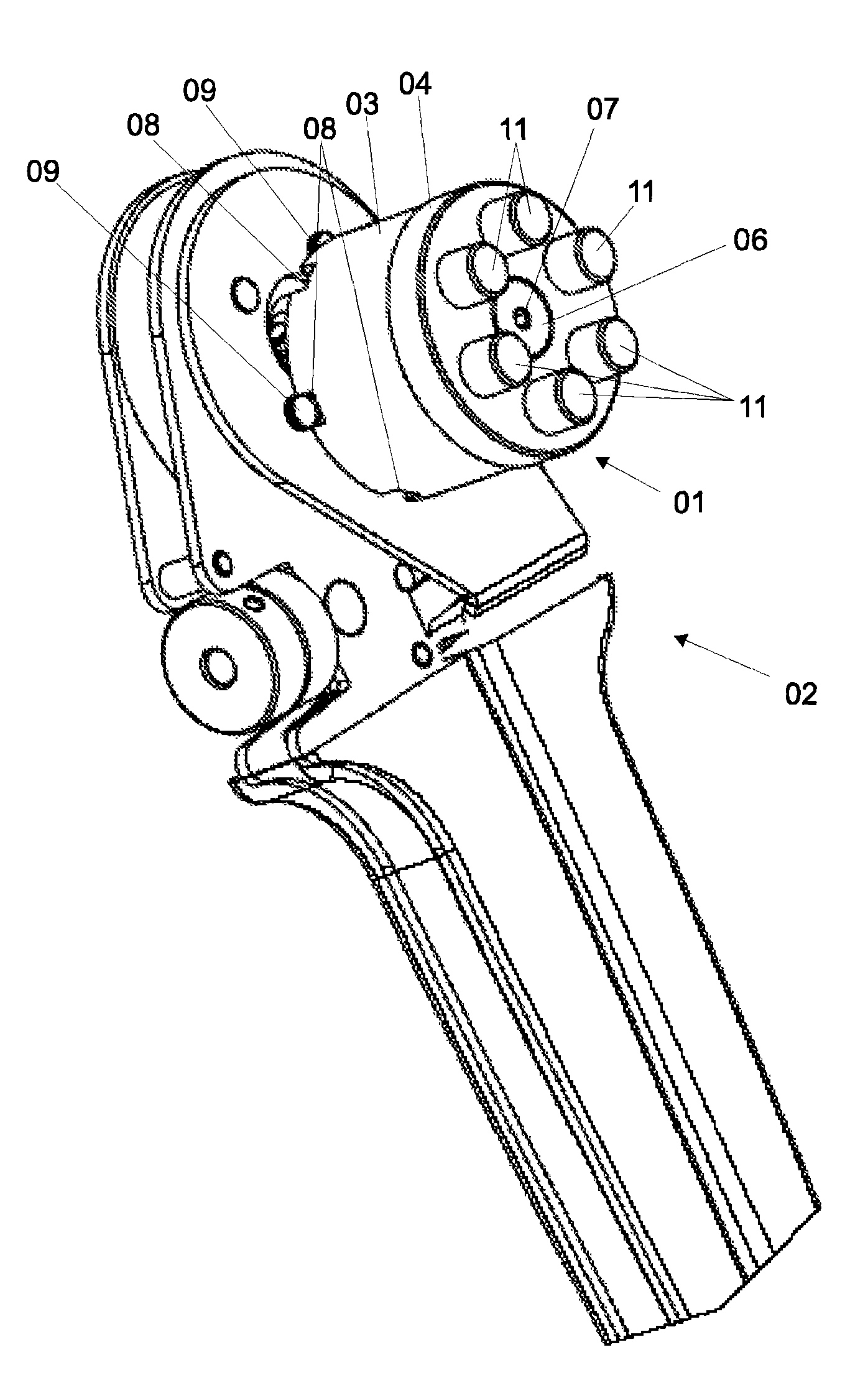
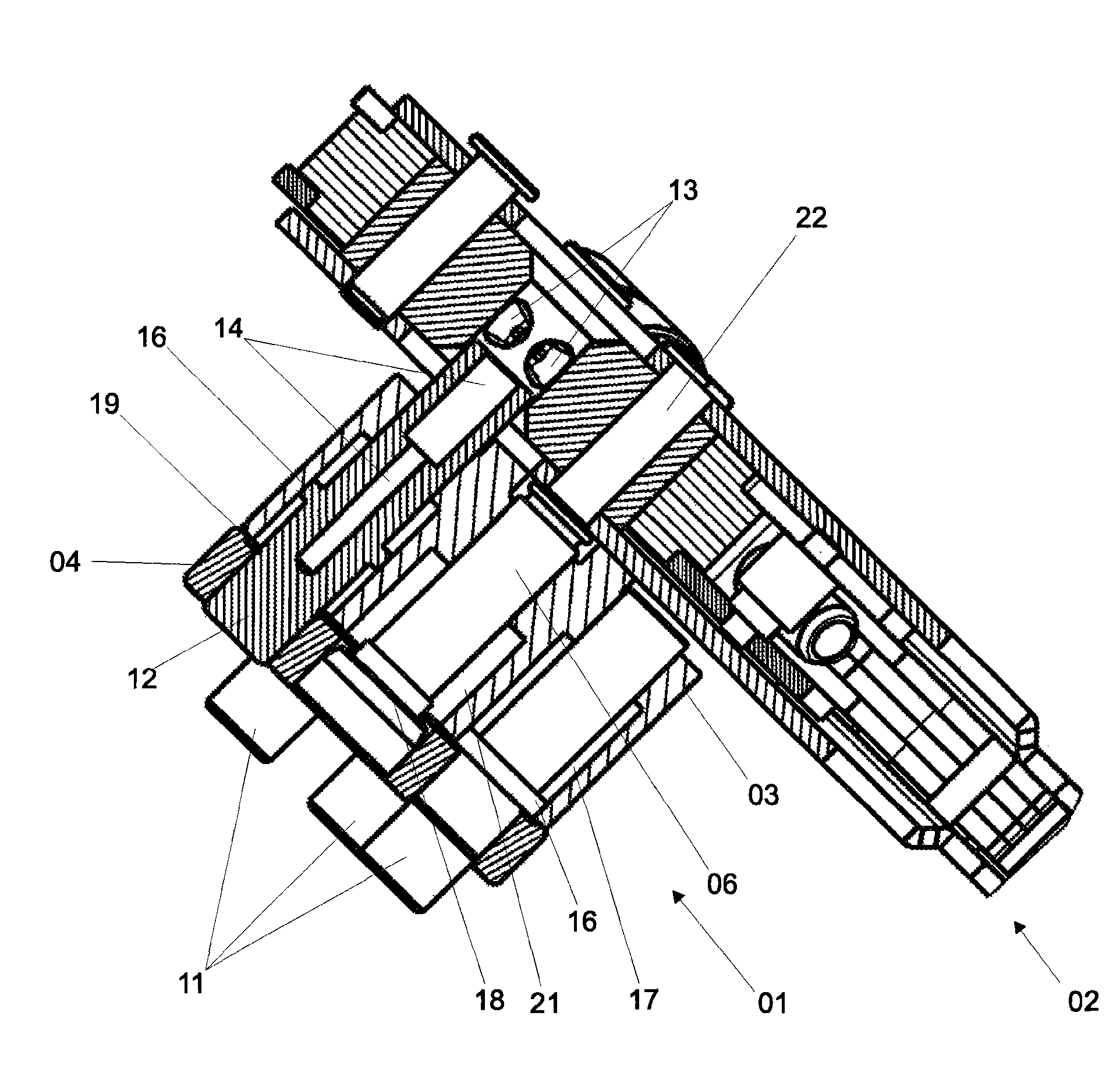
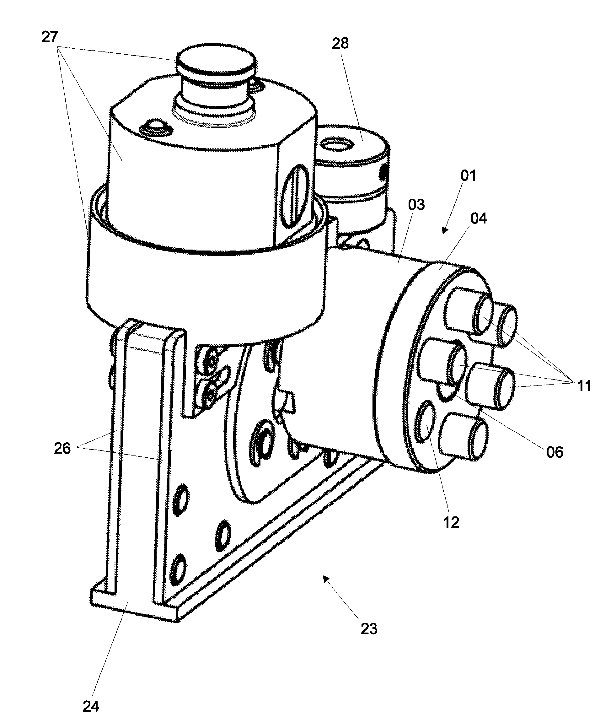
[0042] figure 1 A preferred embodiment of the positioning device 01 according to the invention is shown, which is mounted laterally on the crimping pliers 02 . The positioning device 01 has a wheel-like carrier head 03 which is closed with a cover 04 . The carrier head 03 has a substantially cylindrical shape. The fixed shaft 06 is located on the axis of the carrier head 03 , and the fixed shaft 06 is screwed onto the crimping pliers 02 . To this end, the fixed shaft 06 has an internal thread, which is screwed to the retaining bolt 22 of the crimping pliers 02 (at figure 2 shown in ). The holding screw is mounted rotatably in the crimping tool 02 , however, it is locked and clamped on the housing by means of a locking ring, so that turning of the holding screw is somewhat more difficult. In order to fix the positioning device 01 on the crimping pliers 02 , the carrier head 03 is pivoted by means of the fixing shaft 06 onto the holding screw. Since the rotation of the hol...


PUM


Abstract

The invention relates to a positioning device for crimping tools. Such positioning devices are suitable for the positioning of an element that is to be pressed relative to the pressing elements of the crimping tool, which are formed by notching elements, crimping plungers or the like. According to the invention, the positioning device (Ol) comprises a support head (03) which is rotatable with respect to the crimping tool (02, 23). A plurality of positioning elements (11, 12) are peripherally arranged in said support head and can be individually displaced in an axial manner in the direction of the crimping tool (02, 23) between an initital position and a working position. The invention also relates to a crimping tool, for example a crimping pliers or a crimping insert for a crimping machine.

Description

technical field [0001] The invention relates to a positioning device (also called a positioner) for crimping tools. Such a positioning device serves to position the element to be pressed relative to the pressing element of the crimping tool, which is formed by a notch element, a crimping punch or the like. Considered as an element to be pressed, for example, is an electrical connecting plug which is to be connected to the conductor by means of a crimping process. Furthermore, the invention relates to a crimping tool, such as a crimping pliers or a crimping insert for a crimping machine, which in each case can be equipped with such a positioning device. Background technique [0002] A positioner for crimping devices is known from EP 0368825 A2, which is particularly suitable for crimping devices with a plurality of punching element pairs. The positioner has, for each punched element pair, a handle element for receiving an electrical connection element. The handle element i...

Claims


Application Information

Patent Timeline
Patent Type & Authority Applications(China)
IPC IPC(8): H01R43/042H01R43/048
CPCH01R43/042H01R43/0421H01R43/0585H01R43/0424H01R43/048
Inventor 霍斯特·诺特纳格尔格哈德·柯尼希迈克尔·布鲁克纳托马斯·瓦格纳
Owner RENNSTEIG WERKZEUGE
Why Eureka
Try Eureka