
Axle protection structure

A protection structure and axle technology, applied in the directions of axles, axles, wheels, etc., can solve the problems of easy breakage of the axle, fuel leakage, and the driver cannot decelerate in time, so as to increase the reaction time, strengthen the power transmission ability, and improve the effect of safety.

Inactive Publication Date: 2018-02-06
CHONGQING ZHANRUI AUTOMOBILE FITTING FACTORY
View PDF0 Cites 2 Cited by
  • Summary
  • Abstract
  • Description
  • Claims
  • Application Information

AI Technical Summary

Problems solved by technology

This causes the axles of engineering transport vehicles or field work vehicles to break easily
After the axle breaks, the vehicle immediately loses its ability to drive, and the driver usually has no time to slow down, which can easily lead to rollover
At the same time, the debris from the broken axle is flying around and can easily penetrate the fuel tank, causing fuel leakage or fire

Method used


Image

  • Axle protection structure

Examples


Embodiment 1

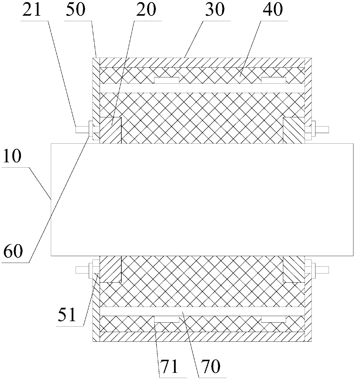
[0027] like figure 1 As shown, an axle protection structure includes an axle 10, a fixing ring 20, a protection tube 30, a filling layer 40 and a connecting flange 50;

[0028] The two fixing rings 20 are sleeved on both ends of the axle 10 oppositely, and the fixing rings 20 are in interference fit with the axle 10; one side of the fixing ring 20 extends axially outward to form a plurality of A fixing rod 21; the fixing rods 21 on the two fixing rings 20 are located on the sides of the two fixing rings 20 away from each other;

[0029] The connecting flange 50 is sleeved on the axle 10, and a through hole 51 is opened on the connecting flange 50, and the fixing rod 21 passes through the through hole 51; the connecting flange 50 passes through the The nut 60 threaded to the fixing rod 21 is fixed on the fixing ring 20;

[0030] The protective tube 30 is sleeved on the axle 10, and the two ends of the protective tube 30 are respectively fixedly connected with the two connecti...

Embodiment 2

[0034] like figure 1 As shown, on the basis of Embodiment 1, this embodiment further includes a connecting rod 70 , and the two ends of the connecting rod 70 are respectively connected to the two connecting flanges 50 .

[0035] The two connecting flanges 50 are connected by the connecting rod 70, so that after the axle 10 breaks, the power transmission capability is strengthened, so that the power can be transmitted from one end of the axle 10 to the other end in a longer period of time, increasing the driver's safety. Reaction time.

Embodiment 3

[0037] like figure 1 As shown, this embodiment is based on Embodiment 2, the connecting rod 70 is located between the inner surface of the protective tube 30 and the outer surface of the axle 10, and the connecting rod 70 penetrates the filling layer 40 .

[0038] The connecting rod 70 runs through the filling layer 40. On the one hand, it can be used to firmly fix the filling layer 40, so as to prevent the filling layer 40 from shaking during the normal running of the vehicle and affect the balance of the axle. On the other hand, after the axle 10 breaks, if the connecting rod 70 breaks thereupon, the fragments produced by the fracture of the connecting rod 70 can be blocked by the filling layer 40, thereby preventing the fragments produced by the fracture of the connecting rod 70 from penetrating the fuel tank. Furthermore, after the axle 10 breaks, the connecting rod 70 also helps to maintain the basic shape of the filling layer 40 without twisting or breaking, so that the...


PUM


Abstract

The invention discloses an axle protection structure, which comprises an axle, a fixed ring, a protective tube, a filling layer and a connecting flange; One side of the shaft extends axially outward to form a plurality of fixed rods; the fixed rods on the two fixed rings are located on the sides of the two fixed rings away from each other; the connecting flange is sleeved on the axle, and a through hole is opened on the connecting flange , the fixed rod goes through the through hole; the connecting flange is fixed on the fixed ring through the nut threaded with the fixed rod; the protective tube is set on the axle, and the two ends of the protective tube are respectively fixedly connected with the two connecting flanges; Between the outer surface of the axle and the inner surface of the protection cylinder, the filling layer is wear-resistant rubber. The invention can slow down the loss of driving force of the vehicle after the axle breaks, and prevent the fragments produced by the breakage of the axle from penetrating the fuel tank.

Description

technical field [0001] The invention relates to the field of automobiles, in particular to an axle protection structure. Background technique [0002] For engineering transport vehicles or field operation vehicles, the working environment is harsh and the road surface fluctuates greatly, causing the axles to bear a huge load. This causes the axles of engineering transport vehicles or field work vehicles to break easily. After the axle breaks, the vehicle immediately loses its ability to drive, and the driver usually has no time to slow down, which can easily lead to rollover. At the same time, the debris from the broken axle is flying around and can easily penetrate the fuel tank, causing fuel leakage or fire. Contents of the invention [0003] The object of the present invention is to overcome the above-mentioned problems of the prior art, and provide an axle protection structure. [0004] The purpose of the present invention is mainly achieved through the following te...

Claims


Application Information

Patent Timeline
Patent Type & Authority Applications(China)
IPC IPC(8): B60B35/00F16C3/02
CPCB60B35/00B60B2900/212F16C3/02
Inventor 唐汉林
Owner CHONGQING ZHANRUI AUTOMOBILE FITTING FACTORY
Learn More