Eureka AIR delivers breakthrough ideas for toughest innovation challenges, trusted by R&D personnel around the world.

Magnetic suspension support

A magnetic levitation and seat plate technology, applied in the field of magnetic levitation, can solve the problems that the integrity and smoothness of the magnetic levitation system cannot be guaranteed, and achieve the effect of ensuring train operation safety, assembly error assurance, integrity and smoothness

Pending Publication Date: 2021-02-05
成都西交华创科技有限公司 +3
View PDF0 Cites 2 Cited by
  • Summary
  • Abstract
  • Description
  • Claims
  • Application Information

AI Technical Summary

Problems solved by technology

[0004] The purpose of the present invention is to provide a magnetic levitation support to solve the problem that the existing magnetic levitation support cannot guarantee the integrity and smoothness of the magnetic levitation system circuit

Method used


Image

  • Magnetic suspension support
  • Magnetic suspension support
  • Magnetic suspension support

Examples


no. 1 example

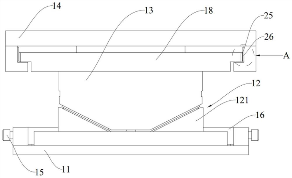
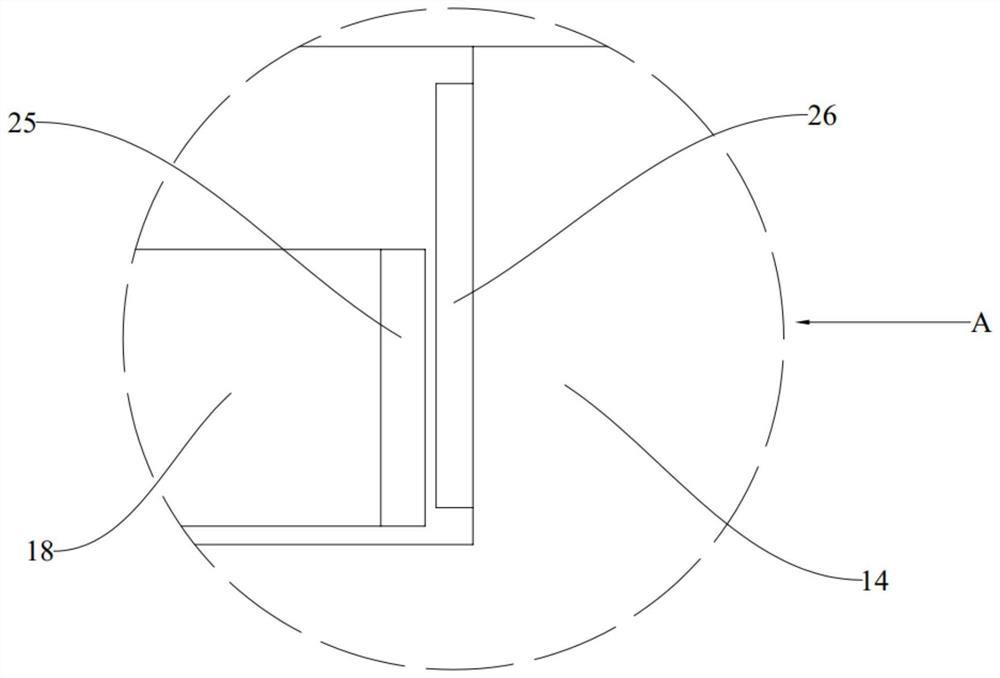
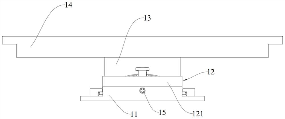
[0045] Such as Figure 1-5 As shown, this embodiment provides a magnetic levitation support, such as used in a vacuum pipeline of a magnetic levitation system. The magnetic levitation support includes a lower seat plate 11 and a position adjusting member 12 . The position adjusting member 12 is slidably arranged on the lower seat plate 11 and can slide relative to the lower seat plate 11 along the transverse direction.

[0046] Optionally, as in Figure 4-7 As shown, the position adjustment member 12 includes two position adjustment sliders 121, and the two position adjustment sliders 121 are arranged symmetrically. The position adjustment sliders 121 are provided with first protrusions 1212 on both sides along the transverse bridge direction. The lower seat plate 11 A second groove 111 cooperating with the first protrusion 1212 is provided on the top, and the first protrusion 1212 can slide relative to the second groove 111 along the transverse direction. The cooperation be...

no. 2 example

[0063] Such as Figure 14 As shown, this embodiment provides a magnetic levitation support. The structure of the magnetic levitation support of this embodiment is basically the same as that of Embodiment 1, the difference is that the magnetic levitation support of this embodiment also includes an upper seat plate retaining strip 27, two Two upper seat plate retaining strips 27 are respectively fixed on the two ends of the upper seat plate 14 along the bridge direction, and one side of the upper seat plate retaining strips 27 is close to the rotating sleeve 18, so that the rotating sleeve 18 and the upper seat plate 14 cannot be opposite in the bridge direction. Move, so that there is no relative movement between the lower seat plate 11 and the upper seat plate 14 in the direction along the bridge. This arrangement enables the load of the vacuum pipeline of the magnetic levitation system to the upper seat plate 14 along the bridge direction to be accurately transmitted to the lo...


PUM


Abstract

The invention belongs to the technical field of magnetic levitation, and discloses a magnetic levitation support which comprises a lower support plate, a position adjusting piece, a middle support plate and an upper support plate. The middle seat plate is arranged on the position adjusting piece, and the position adjusting piece can move in the transverse bridge direction so as to adjust the height of the middle seat plate and / or the position of the middle seat plate in the transverse bridge direction; the upper seat plate is arranged on the middle seat plate in a sliding mode and can slide inthe bridge direction. When the position of a vacuum pipeline or a lower supporting structure changes in the installation process or the subsequent use process of a magnetic suspension system line, the integrity and smoothness of the line in the bridge direction can be guaranteed through relative sliding between the upper base plate and the middle base plate; the integrity and smoothness of a linein the vertical direction and the transverse bridge direction can be guaranteed by adjusting the position adjusting pieces, and the train operation safety is guaranteed.

Description

technical field [0001] The invention relates to the technical field of magnetic suspension, in particular to a magnetic suspension support. Background technique [0002] The low-vacuum pipeline high-speed maglev system has the advantages of high speed, low energy consumption, and low pollution. It is of great significance for promoting regional green development and building a new transportation mode that is clean, low-carbon, safe, efficient, and green. Due to the characteristics of high-speed operation of high-speed maglev trains, there are strict requirements on the integrity and smoothness of the line. In order to ensure the integrity and smoothness of the maglev system line, the maglev support is used as a transition connection between the vacuum pipe of the maglev system and the lower support structure. The device must be able to correct the assembly error caused by the on-site laying process to ensure the laying accuracy of the line, and be able to adapt to the positi...

Claims


Application Information

Patent Timeline
IPC IPC(8): E01B25/30
CPCE01B25/30
Inventor 金朝辉蒋文希桂鉴臣张兴张波赵志磊王念才马志远魏春晶赵九平
Owner 成都西交华创科技有限公司
Why Eureka
Eureka Blog
Learn More