Composite magnetism gathering type permanent magnet guide rail mechanism applicable to high-speed superconductivity magnetic suspension system

A magnetic levitation and permanent magnet technology, which is applied in electric traction, electric vehicles, transportation and packaging, etc., can solve the problems of low utilization rate of magnetic energy, redundant structure of permanent magnet rails, increased cost, etc., to achieve variable structure, improved performance, The effect of ensuring the strength of the magnetic field

Active Publication Date: 2013-06-12
BEIJING AEROSPACE CENTURY SUPERCONDUCTING TECH
View PDF4 Cites 11 Cited by
  • Summary
  • Abstract
  • Description
  • Claims
  • Application Information

AI Technical Summary

Problems solved by technology

Under the current technical conditions, the lower surface of the permanent magnet guide rail needs to be connected with the basic bearing parts, so only the magnetic field energy on the upper surface

Method used


Image

  • Composite magnetism gathering type permanent magnet guide rail mechanism applicable to high-speed superconductivity magnetic suspension system
  • Composite magnetism gathering type permanent magnet guide rail mechanism applicable to high-speed superconductivity magnetic suspension system
  • Composite magnetism gathering type permanent magnet guide rail mechanism applicable to high-speed superconductivity magnetic suspension system

Examples


Embodiment 1

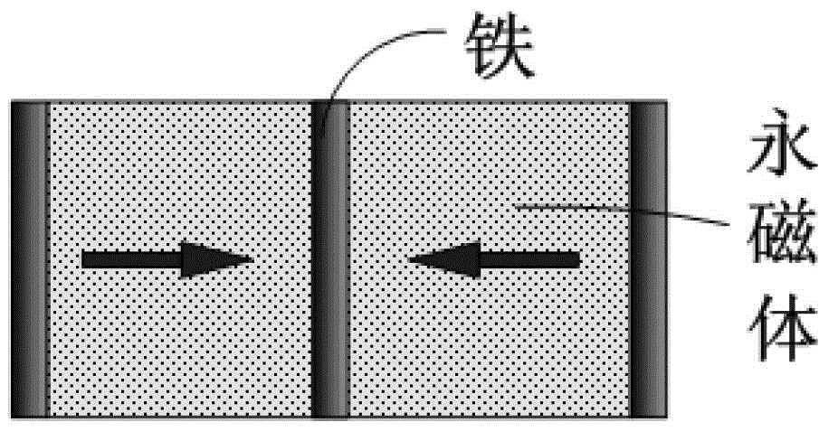
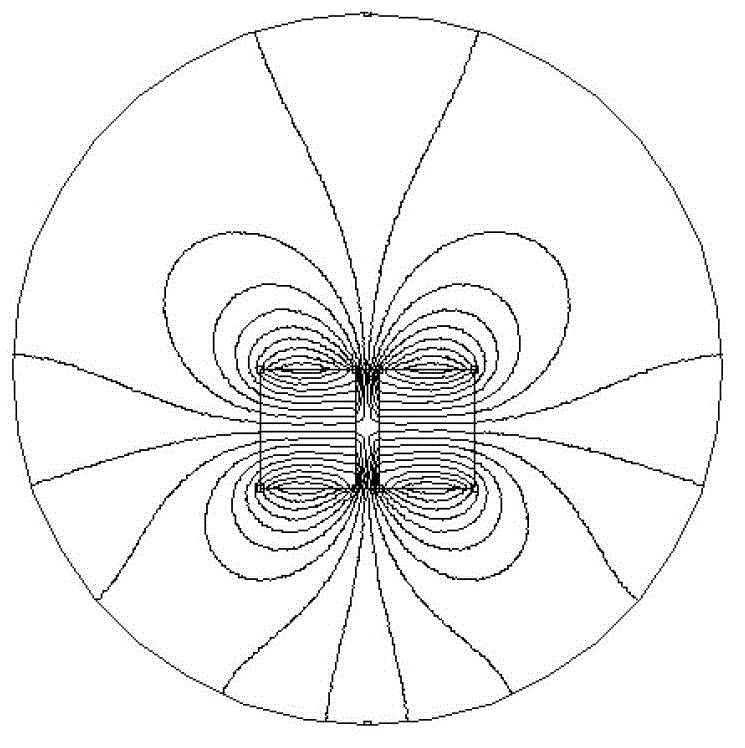
[0045] Embodiment 1 uses ferromagnetic materials as the main magnetic poles, and the high permeability of ferromagnetic materials can be used to suppress the damage caused by the processing and assembly of permanent magnetic materials and the installation of permanent magnetic mechanisms. image 3 The magnetic field inhomogeneity in the Y direction of the permanent magnet guide shown in . image 3 The inhomogeneity of the magnetic field in the Y direction of the medium permanent magnet guide rail may generate eddy currents inside the high-temperature superconducting block and cause magnetic flux movement in some applications, such as ultra-high-speed operation, resulting in loss and heat, reducing the suspension system. In severe cases, the accumulated heat may even cause partial failure inside the high-temperature superconducting bulk material, directly threatening the safety of the suspension system. Therefore, Embodiment 1 is a high-efficiency permanent magnet guide rail me...


PUM


Abstract

The invention discloses a composite magnetism gathering type permanent magnet guide rail mechanism applicable to a high-speed superconductivity magnetic suspension system. The composite magnetism gathering type permanent magnet guide rail mechanism comprises a main magnetism gathering pole formed by a plurality of ferromagnetic materials, a permanent magnet contraposition combination formed by a plurality of permanent magnets, and a permanent magnet guide combination formed by a plurality of permanent magnets. The composite magnetism gathering type permanent magnet guide rail mechanism is characterized in that the main magnetism gathering pole can gather the main magnetic circuit or the main magnetic energy of the permanent magnet guide rail and diffuses towards the space, and the high magnetic conductivity is favorable for inhibiting longitudinal magnetic field gradient; the permanent magnet contraposition combination generates strong magnetic pressure by utilizing the mutual repulsion effect between the magnetic poles of each permanent magnet; and the permanent magnet guide combination has the effects of auxiliarily gathering magnetism and guiding the magnetic circuit, and guides and diffuses the magnetic energy of the permanent magnets to the upper surface of the guide rail and the above region by utilizing the magnetization directionality of the permanent magnets. The composite magnetism gathering type permanent magnet guide rail mechanism obviously improves the utilization ratio of the permanent magnet guide rail magnetic field on the basis of guaranteeing the requirement of the magnetic suspension system on the magnetic field intensity, effectively stabilizes the longitudinal magnetic field gradient caused by the errors or defects of the permanent magnets, and guarantees the safety and the stability of the high-temperature superconductivity magnetic suspension system during operation at high speed and ultrahigh speed.

Description

technical field [0001] The invention belongs to the high-temperature superconducting magnetic levitation technology, and relates to a compound magnetism-concentrating permanent magnet guide rail mechanism suitable for a high-speed superconducting magnetic levitation system. Background technique [0002] Compared with the electromagnetic levitation (EMS) and electric levitation (EDS) technologies based on electromagnetic attraction and electromagnetic induction repulsion respectively, the high-temperature superconducting magnetic levitation technology relies on the electromagnetic induction between the high-temperature superconducting bulk material and the external magnetic field excitation. The permanent current realizes stable self-suspension without active control, simple structure, and reliable principle. It has become one of the ideal choices for practical magnetic levitation technology. The field has broad application prospects, and its low energy consumption, high reli...

Claims


Application Information

Patent Timeline
IPC IPC(8): B60L13/04
Inventor 刘伟王家素王素玉马光同郑珺
Owner BEIJING AEROSPACE CENTURY SUPERCONDUCTING TECH
Why Eureka
Try Eureka