Electric heating fused cleaning device for modulating wave oil tubes and sucker rods

A sucker rod and modulated wave technology, used in isolation devices, cleaning appliances, wellbore/well components, etc., can solve the problems of increased pipe washing time and cost, large floor space, and easy generation of pollution along the way.

Inactive Publication Date: 2014-08-20
CHINA UNIV OF PETROLEUM (EAST CHINA)
View PDF5 Cites 0 Cited by
  • Summary
  • Abstract
  • Description
  • Claims
  • Application Information

AI Technical Summary

Problems solved by technology

[0002] At present: during oil well operations, it is necessary to clean various types of tubing and sucker rods extracted from ultra-high pouring oil, ultra-heavy oil, and ultra-high waxy oil wells. The traditional method is to pull back the extracted tubing and sucker rods The pipe washing factory performs unified cleaning or uses a pump truck combined with a steam truck to clean on site, so as to achieve the purpose of cleaning and checking the quality of the oil pipe and sucker rod; the disadvantage is that the unified cleaning requires long-distance transportation, and it is easy to be bumped and damaged during the transportation process. Oil pipes and sucker rods require a large number of staff, resulting in high handling and management costs, large floor space, and easy pollution along the way during transportation, which is not conducive to environmental protection; pump trucks combined with steam trucks on site The sewage and dirty oil produced by the stab washing method will also seriously pollute the well site. The cleaning efficiency is low, the cost is high, and the effect is poor. The cost will increase by tens of times or the cleaning work will not be completed at all

Method used


Image

  • Electric heating fused cleaning device for modulating wave oil tubes and sucker rods
  • Electric heating fused cleaning device for modulating wave oil tubes and sucker rods
  • Electric heating fused cleaning device for modulating wave oil tubes and sucker rods

Examples


Embodiment Construction

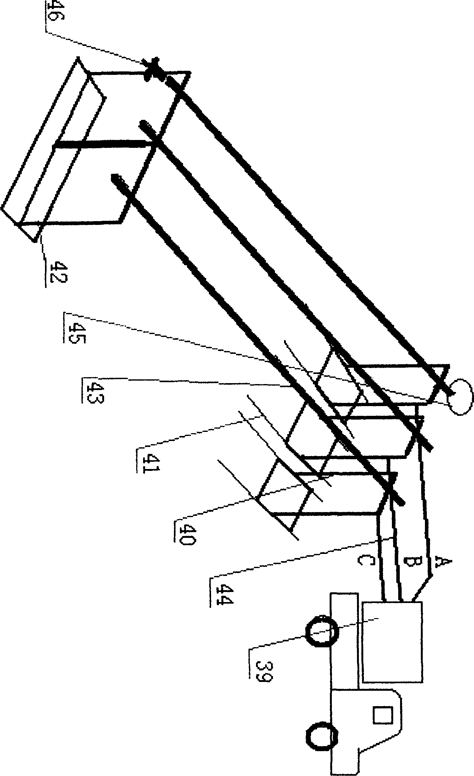
[0012]A further description of the electric heating melting washing device for modulated wave oil pipe and sucker rod of the present invention: an electric heating melting washing device for modulated wave oil pipe and sucker rod, the device is mainly composed of a vehicle-mounted wave modulating power supply, a pneumatic electrode clamp frame, an electrode clamp frame guide rail, pneumatic lifting electric clamp frame, pneumatic pipe cleaner, crude oil recovery device, air control circuit and primary and secondary power supply circuits; The phase power frequency alternating current is automatically converted into a three-phase modulated wave current lower than 36V, and is respectively connected to the terminals of the three electrode clamps 40 of A, B, and C by the secondary cables 44, and the pneumatic lift clamp 42 connects the three poles The oil pipe 43 as an electrothermal converter forms a good electrical connection, and uses it as the middle phase of the Y-shaped circui...


PUM


Abstract

The invention relates to an on-site electric heating cleaning device for various types of oil tubes and sucker rods pulled out of super high condensate oil wells, super heavy oil wells and super-high wax-bearing oil wells during oil well operation, in particular to an electric heating fused cleaning device for modulating wave oil tubes and sucker rods. The device of the invention is mainly composed of a vehicle-mounted wave production power supply, a pneumatic electrode clamping frame, an electrode clamping frame guide rail, a pneumatic lifting electric clamping frame, a pneumatic tube cleaner, a crude oil recovery device, a pneumatic control circuit, a first supply circuit and a second supply circuit, wherein, the electrode clamping frame is used for inputting electrodes and serves as a pivot; the electrode clamping frame and the pneumatic lifting frame lift and support heated and cleaned oil tubes or sucker rods so as to prevent the body of the oil tube or the sucker from contacting with other electric conduction objects to cause short circuit; the vehicle-mounted wave production power supply is used for intelligently supplying power; the crude oil recovery devices, such as the pneumatic tube cleaner, a woven bag support frame and the like are used for receiving melted rude oil and waxiness in and out of the oil tubes or sucker rods.

Description

technical field [0001] The invention relates to an on-site electrothermal cleaning device for various types of oil pipes and sucker rods extracted from ultra-high pouring oil, ultra-heavy oil, and ultra-high waxy oil wells during oil well operations, especially: a modulated wave oil pipe and sucker rod Electric melting washing device. Background technique [0002] At present: during oil well operations, it is necessary to clean various types of tubing and sucker rods extracted from ultra-high pouring oil, ultra-heavy oil, and ultra-high waxy oil wells. The traditional method is to pull back the extracted tubing and sucker rods The pipe washing factory performs unified cleaning or uses a pump truck combined with a steam truck to clean on site, so as to achieve the purpose of cleaning and checking the quality of the oil pipe and sucker rod; the disadvantage is that the unified cleaning requires long-distance transportation, and it is easy to be bumped and damaged during the tr...

Claims


Application Information

Patent Timeline
Patent Type & Authority Patents(China)
IPC IPC(8): E21B37/00E21B36/04
Inventor 李载敏蔺爱国孙洪涛王作启史建英王琦陈帆李寅东
Owner CHINA UNIV OF PETROLEUM (EAST CHINA)
Why Eureka
Try Eureka