
Intake manifold

A technology of intake manifold and intake pipe, which is applied in combustion air/combustion-air treatment, engine components, machine/engine, etc. Problems such as poor performance to achieve the effect of improving allocation performance

Inactive Publication Date: 2009-12-09
AISAN IND CO LTD
View PDF1 Cites 11 Cited by
  • Summary
  • Abstract
  • Description
  • Claims
  • Application Information

AI Technical Summary

Problems solved by technology

[0004] However, in the above-mentioned intake manifold, the throttle valve installation part is provided near the surge tank, and the distance from the throttle valve device to the surge tank is very short.
Therefore, there is a problem of poor distribution of suction air to each manifold
In addition, blow-by gas, evaporated fuel, or EGR gas, etc. flow into the intake manifold, and the distribution of these gases to each intake manifold is also poor.
That is, the distribution performance to each intake branch pipe is poor, and it is difficult to improve the performance of the internal combustion engine

Method used


Image

  • Intake manifold
  • Intake manifold
  • Intake manifold

Examples


Embodiment Construction

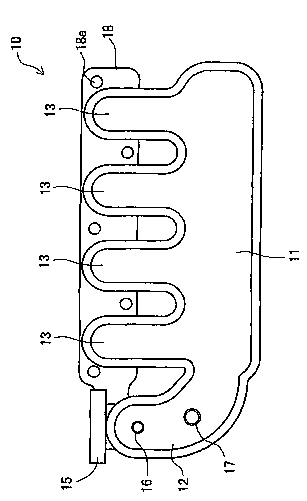
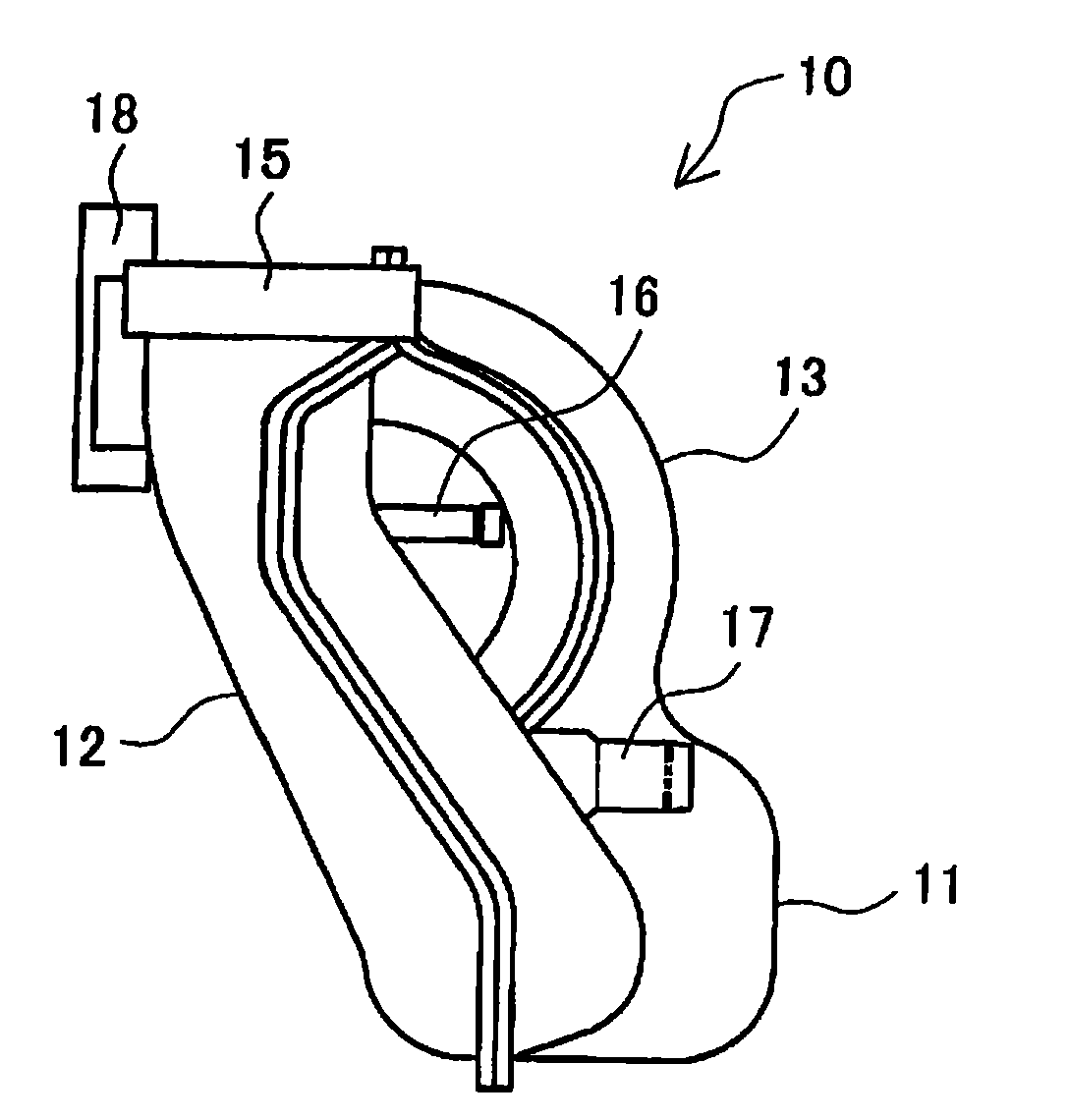
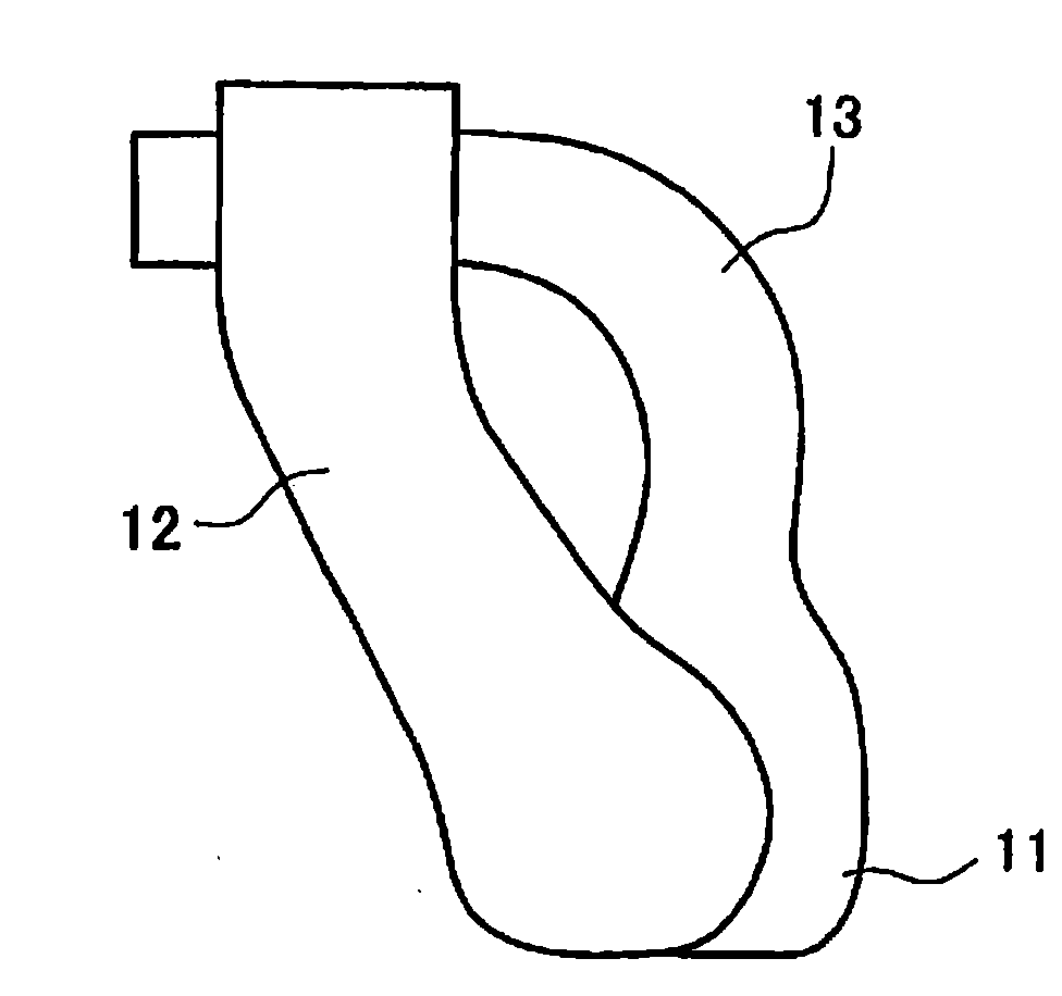
[0031] Hereinafter, the best mode for realizing the intake manifold of the present invention will be described in detail based on the drawings. In this embodiment, a case where the present invention is applied to an intake manifold used in an intake system of a 4-cylinder gasoline engine will be described.

[0032] Here, refer to Figure 1 ~ Figure 3 The intake manifold of this embodiment will be described. figure 1 It is a front view showing a schematic structure of the intake manifold of the embodiment. figure 2 It is a side view showing the schematic structure of the intake manifold of the embodiment. image 3 It is a figure which schematically shows the duct space formed in the intake manifold of embodiment.

[0033] Such as figure 1 , figure 2 As shown, the intake manifold 10 includes a surge tank 11 , an air intake pipe 12 and four air intake branch pipes 13 . The intake manifold 10 is a resin intake manifold called a resin intake manifold, and supplies air (inta...


PUM


Abstract

The invention provides an intake manifold capable of improving distribution property of suction for each suction manifold. The intake manifold (10) comprises a stable pressure tank (11) for temporarily storing suction; a plurality of the bent suction manifold (13) for connecting the stable pressure tank (11) with each air cylinder of an engine; an engine mounting flange (18) arranged at front of each suction manifold (13) in order that the suction manifolds (13) are mounted on the engine; an air damper mounting part (15) arranged nearby the engine mounting flange (18) in order to mount an airdamper device; an air suction pipe (12) used for connecting the air damper mounting part (15) with the stable pressure tank (11).

Description

technical field [0001] The present invention relates to an intake manifold provided on an intake system of an internal combustion engine to supply intake air (intake air) to the internal combustion engine. Background technique [0002] In an intake system of an internal combustion engine, an intake manifold is provided for distributing and supplying intake air to each cylinder of the internal combustion engine. In recent years, an intake manifold integrated by joining a plurality of molded bodies has been put into practical use. An example of such an intake manifold is disclosed in Patent Document 1, for example. The intake manifold disclosed here has a two-part structure, and is formed by joining a throttle valve mounting portion to which a throttle device is attached, a lower molded body forming a manifold lower split body, and an upper molded body forming a manifold upper split body. form an integrated structure. [0003] Patent Document 1: Japanese Patent Application ...

Claims


Application Information

Patent Timeline
Patent Type & Authority Applications(China)
IPC IPC(8): F02M35/104
Inventor 岩田伸二
Owner AISAN IND CO LTD
Learn More