Direct-current power-driven vacuum pump used for automobile

An electric vacuum pump, direct current technology, applied in the direction of pumps, machines/engines, rotary piston pumps, etc., can solve the problems of unfavorable miniaturization design of cars, enlarged vacuum pump structure, long vacuuming time, etc. The effect of low resistance and short vacuuming time

Inactive Publication Date: 2009-12-09
衢州新业汽车部件有限公司
View PDF0 Cites 2 Cited by
  • Summary
  • Abstract
  • Description
  • Claims
  • Application Information

AI Technical Summary

Problems solved by technology

[0003] However, the above-mentioned vacuum pump has the following problems in actual use: the liquid storage tank is separated from the pump body, and is arranged on one side of the pump body, and the two are connected by a pipeline. Make the entire vacuum pump structure too bulky and heavy, which is not conducive to the new concept of car miniaturization design

Method used


Image

  • Direct-current power-driven vacuum pump used for automobile
  • Direct-current power-driven vacuum pump used for automobile
  • Direct-current power-driven vacuum pump used for automobile

Examples


Embodiment Construction

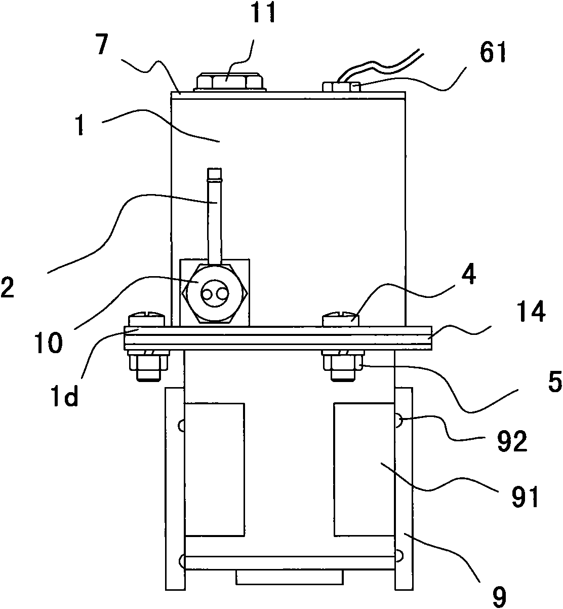
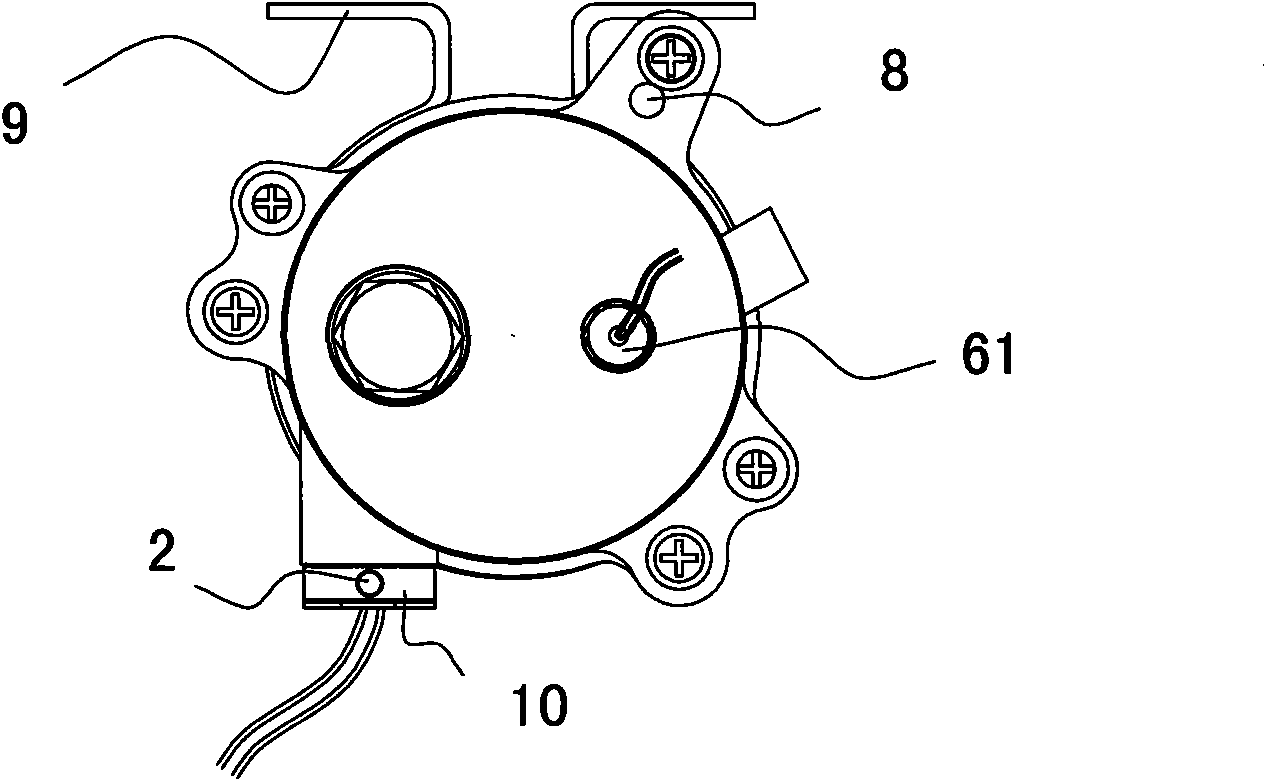
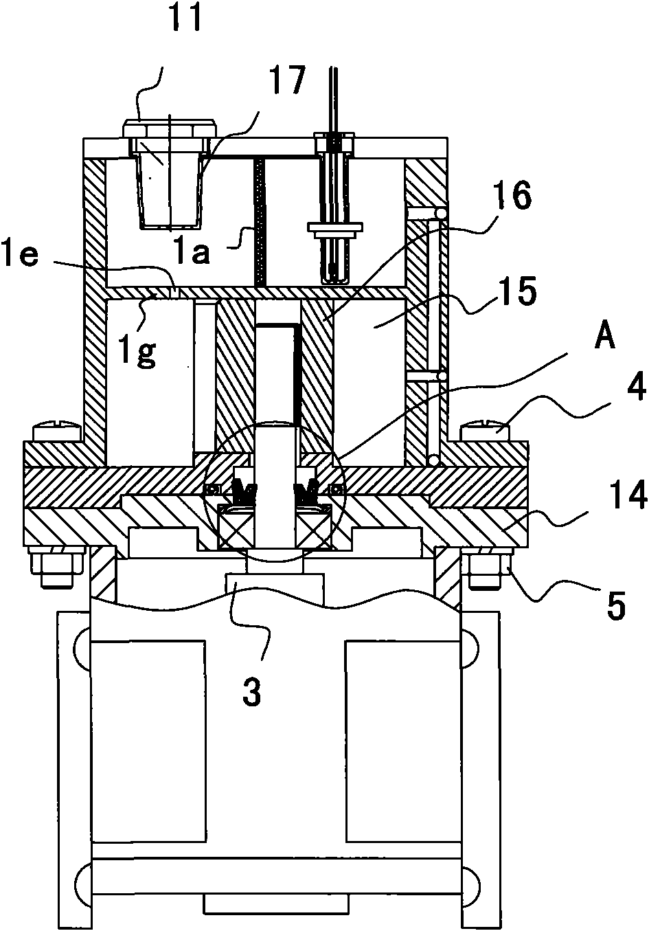
[0019] see figure 1 , and combined with figure 2 . Viewed from the outside, the vacuum pump consists of a pump body and a DC motor 3 from top to bottom. The pump body is composed of a split pump body cover 7, a pump body wall 1 and a lower casing 14, wherein the pump body cover 7 and the pump body wall 1 form an upper casing. The circumference of the circular pump body cover 7 is surrounded by several fixed through holes, which are matched with it. The upper end surface of the pump body wall 1 is provided with threaded connection sink holes, and the pump body cover 7 and the pump body wall 1 are connected by bolts. into a whole. The pump body cover 7 is also provided with a filter screen installation hole 71 and a liquid level sensor installation hole 72 , and these two holes are used to receive the muffler 11 and the installation nut 61 .

[0020] The DC motor 3, the lower casing 14 and the pump body wall 1 pass through the mounting flange 1d at the lower end of the pump...


PUM


Abstract

The invention relates to a direct-current power-driven vacuum pump used for an automobile, which comprises a pump body, a direct-current machine and the like, wherein the pump body comprises a pump body cover, a pump body wall and a lower housing; an inner chamber formed by walls of the pump body is internally provided with a radial clapboard so that a liquid storage chamber and a vacuum chamber are formed in the inner chamber. The liquid storage chamber is internally provided with an oil gas separating mesh which divides the liquid storage chamber into a left chamber and a right chamber; the left chamber is internally provided with an oil filling port and a silencer; and the right chamber is internally provided with a liquid level inductor. The liquid storage chamber and the vacuum chamber are connected by utilizing a passageway internally arranged in the walls of the pump body to serve as an oil-gas work channel. A power circuit of the direct-current machine is also connected with a controller. The product has the advantages of small oil line resistance, low noise, short vacuum-pumping time, compact and cleverish structure and liquid position displaying alarm and being in line with new concepts of car design. In addition, the controller always keeps vacuum pressure in a setting proper normal operation range, thus not only increasing safety performance of vehicles, but also being beneficial to energy conservation.

Description

【Technical field】 [0001] The invention relates to a DC electric vacuum pump for automobiles. 【Background technique】 [0002] At present, due to the rapid development of cars powered by electric power, hybrid power and other new energy sources, it is difficult to adapt to the existing brake vacuum booster that uses the engine as the vacuum source. The main reasons are: first, electric power is used as the power source Because the car itself does not need an engine, and the second is that the car with hybrid power as the power source has an engine, but when the engine is working in a gap, the brake vacuum booster connected to the engine manifold cannot obtain a vacuum source, resulting in existing Vacuum booster does not work. In order to solve this problem, the Chinese Patent No. 2007201816065 "A DC Electric Vacuum Pump for Automobiles" came into being and proposed an improvement. The car DC electric vacuum pump structure of this scheme includes a mounting bracket, a pump b...

Claims


Application Information

Patent Timeline
IPC IPC(8): F04C25/02F04C28/00F04C18/344
Inventor 赵国伟
Owner 衢州新业汽车部件有限公司
Why Eureka
Try Eureka