Composite damper

A shock absorber and active shock absorber technology, applied in the direction of shock absorbers, springs/shock absorbers, shock absorbers, etc., can solve problems such as failure, shock absorption failure, and heat dissipation difficulties, and achieve frequency characteristics that can be adjusted and vibration Energy-reducing, wide-ranging effects

Inactive Publication Date: 2011-01-19
LUOYANG INST OF ELECTRO OPTICAL EQUIP OF AVIC
View PDF0 Cites 0 Cited by
  • Summary
  • Abstract
  • Description
  • Claims
  • Application Information

AI Technical Summary

Problems solved by technology

It can be seen that the shock absorber drives the piston rod 14 to achieve shock absorption through the piezoelectric ceramic stack 15, the piston 13 and the hydraulic displacement expander 12. The overall structure is relatively complicated, and the incompressible hydraulic displacement expander 12 The liquid may also leak during use, affecting the shock absorption effect or even causing shock absorption failure
In addition, the damping elastic body 16 superimposed on the shock absorber is made of rubber material, the frequency characteristics are greatly affected by temperature, and heat dissipation is difficult, and it is easy to age and cause the entire shock absorber to fail, thus affecting the overall performance and performance of the shock absorber. life
In addition, the existing piezoelectric ceramic composite shock absorber can only withstand compressive stress, but cannot bear tensile stress. The piezoelectric ceramic actuator can only work in one direction, and it works when the displacement is extended, and it does not work when it is shortened.

Method used


Image

  • Composite damper
  • Composite damper
  • Composite damper

Examples


Embodiment Construction

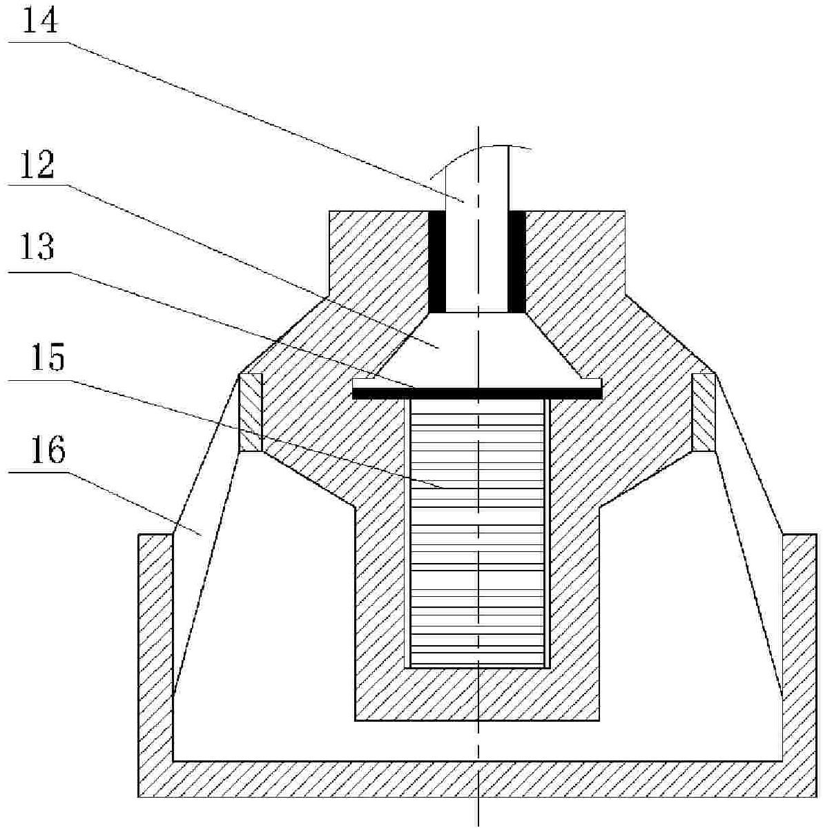
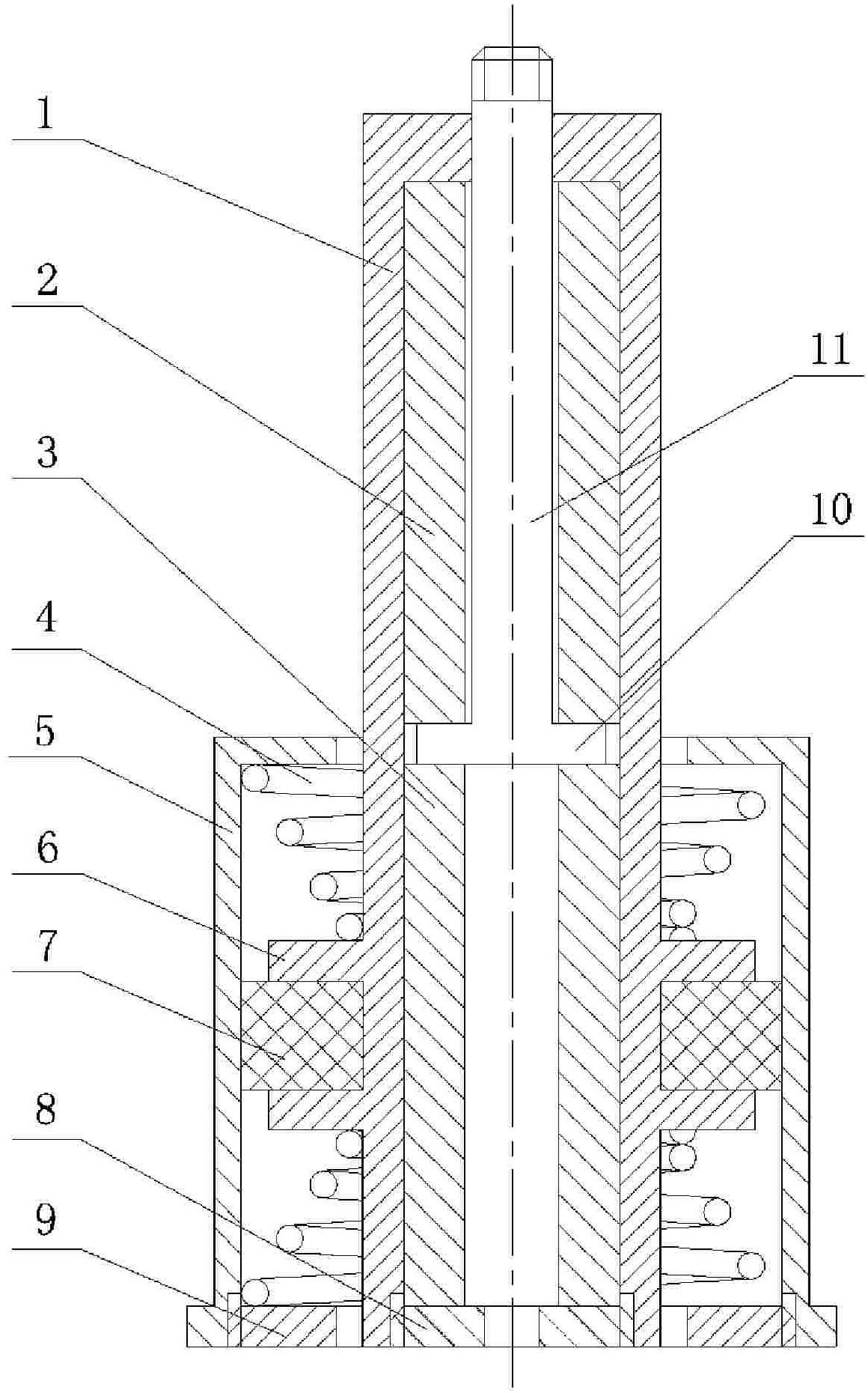
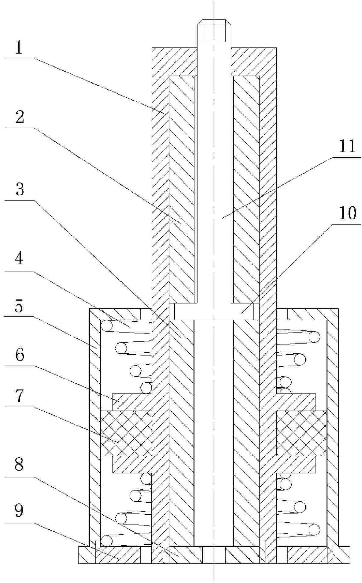
[0018] Such as figure 2 As shown, the composite shock absorber provided by the present invention includes an active shock absorber and a passive shock absorber, wherein the active shock absorber includes an active housing and a push rod 11 slidably inserted on the active housing, and the active housing can be formed by The active casing body 1 and the active casing cover 8 are formed by screw connection. The radial baffle plate 10 on the push rod 11 is located in the active casing and divides the inner cavity of the active casing into upper and lower cavities. There are upper and lower piezoelectric ceramic stacks 2 and 3 respectively for forward and reverse driving push rods, and a damping slot 6 is provided on the outer wall of the active housing; the passive shock absorbing device includes The passive housing is also composed of a passive housing body 5 and a passive housing cover 9 spirally connected, the inner wall of the passive housing is in contact with the outer wall...


PUM


Abstract

The invention relates to a composite damper, which comprises an active damper and a passive absorber. The active damper comprises an active shell and a push rod glidingly inserted into the active shell; a radial baffle plate of the push rod is positioned inside the active shell and divides an inner cavity of the active shell into an upper cavity and a lower cavity; two cavities are provided with an upper piezoelectric ceramic stack and a lower piezoelectric ceramic stack respectively which are used for driving the push rod in a positive direction and a reverse direction; and the passive damper is connected in series with the active shell through an elastomer. The damper can realize bidirectional active damping, has adjustable frequency property and more stable and reliable damping performance, is adaptive to wider temperature range and has smaller drifting of the frequency property; simultaneously, the active damper can cut back low-frequency line spectrum vibration; the passive damper can cut back random vibration and middle-high frequency line spectrum vibration; therefore, the maximal cutback of vibration energy in full frequency band is realized.

Description

technical field [0001] The invention belongs to the technical field of shock absorbers, in particular to an active and passive composite shock absorber. Background technique [0002] At present, the application fields of passive shock absorbers are becoming wider and wider, but the frequency characteristics of existing passive shock absorbers cannot be adjusted, and it is difficult to meet the technical requirements of light weight, small size, compact structure and full-frequency vibration signal reduction. For high-frequency vibration, its reduction effect is relatively good, but for low-frequency vibration, its application range is limited due to its bulky size and heavy weight; and with the development of drivers based on new functional materials, many active reduction devices based on new functional materials The shock absorber came into being. Although it enriches the application range of the shock absorber and meets the technical requirements of some special fields, t...

Claims


Application Information

Patent Timeline
Patent Type & Authority Patents(China)
IPC IPC(8): F16F13/06
Inventor 李树立陈超丁玲纪洁于方德
Owner LUOYANG INST OF ELECTRO OPTICAL EQUIP OF AVIC
Why Eureka
Try Eureka