
Light guide plate and backlight module

A technology of a backlight module and a light guide plate, applied in the field of light guide plates, can solve the problems of insufficient light intensity, influence of sign display effect, high manufacturing cost, and achieve the effect of reducing manufacturing cost

Inactive Publication Date: 2009-12-09
COMPAL ELECTRONICS INC
View PDF0 Cites 2 Cited by
  • Summary
  • Abstract
  • Description
  • Claims
  • Application Information

AI Technical Summary

Problems solved by technology

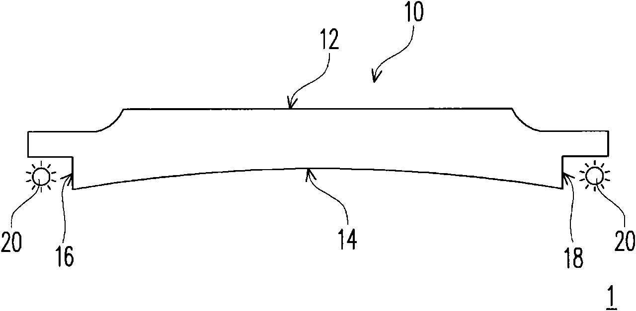
However, the light will produce total reflection on the light-emitting surface 12
Therefore, it is known that the light emitting brightness of the light emitting surface 12 of the known light guide plate 10 is uneven and the light emitting intensity of the light emitting surface 12 is insufficient, which affects the display effect of the logo.
[0005] At present, the way to solve the above shortcomings is to attach a diffuser (not shown) on the light-emitting surface 12 or to form a diffusing agent on the light-emitting surface 12 to solve the problem of uneven light brightness, and to arrange a reflective sheet (not shown) under the bottom surface 14. Shown) to solve the problem of insufficient light intensity
However, the manufacturing cost of the known backlight module 1 as a whole is relatively high

Method used


Image

  • Light guide plate and backlight module
  • Light guide plate and backlight module
  • Light guide plate and backlight module

Examples


Embodiment Construction

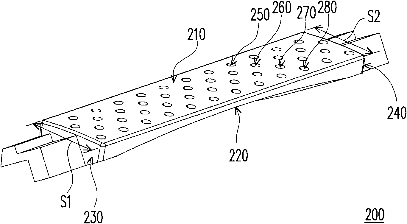
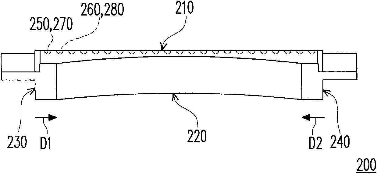
[0057] Figure 2A A three-dimensional schematic view of a light guide plate according to an embodiment of the present invention is shown, Figure 2B draw Figure 2A The side schematic diagram of the light guide plate, Figure 2C draw Figure 2A A partial top view schematic diagram of the light guide plate. Please also refer to 2A, Figure 2B and Figure 2C The light guide plate 200 in this embodiment has a light-emitting surface 210, a bottom surface 220 opposite to the light-emitting surface 210, and a first light-incident surface 230 and a second light-incident surface that connect the light-emitting surface 210 and the bottom surface 220 and are opposite to each other. 240. In this embodiment, the material of the light guide plate 200 is, for example, polymethylmethacrylate (PMMA) or polycarbonate (polycarbonate, PC), and is formed by injection molding.

[0058] The bottom surface 220 gradually approaches the light emitting surface 210 along a first direction D1 away f...


PUM


Abstract

The invention discloses a light guide plate and a backlight module. The light guide plate is provided with a light-emitting surface, a bottom surface, a first incident light surface and a second incident light surface, wherein the bottom surface opposite to the light-emitting surface gradually closes to the light-emitting surface along a first direction far away from the first incident light surface and a second direction far away from the second incident light surface or gradually keeps away from the light-emitting surface along the first direction and the second direction; the first incident light surface and the second incident light surface are connected with the light-emitting surface and the bottom surface and are opposite to each other; the light guide plate comprises a plurality of first recess parts and second recess parts, which are configured on the light-emitting surface, wherein the first recess parts are online arrayed on a first shaft, the second recess parts are online arrayed on a second shaft, the first shaft line is parallel and adjacent to the second shaft line, the first shaft line is perpendicular to the first incident light surface and the second incident light surface, and the second recess parts are formed on a plurality of orthographic projections online formed on the first shaft and are alternately arrayed with the first recess parts.

Description

technical field [0001] The present invention relates to a backlight module, and in particular to a light guide plate suitable for the backlight module. Background technique [0002] With the advancement of technology, computers have become an indispensable tool in our daily life. At present, most of the computers on the market are of standardized standard design, so some manufacturers have made breakthroughs in this unchanging computer product, such as adding a manufacturer’s logo (mark) to the surface of the computer casing (casing) to enhance the additional value of the product. value. Since the logo is only formed on the housing by drawing or engraving, a backlight module is arranged in the housing and corresponding to the position of the logo to illuminate the logo so that the logo can be displayed. [0003] Please refer to figure 1 , which shows a schematic side view of a known backlight module. The known backlight module 1 includes a light guide plate 10 and two li...

Claims


Application Information

Patent Timeline
Patent Type & Authority Applications(China)
IPC IPC(8): F21V8/00G09F13/04
Inventor 陈弘基曹家德花仲正赖钟国
Owner COMPAL ELECTRONICS INC
Learn More