Shooting auxiliary training system and image-based bulls eye positioning method

A training system and target positioning technology, which is applied in the field of shooting auxiliary training system, can solve the problems of complex equipment, many adjustment links, backward circuit design, etc., and achieve the effect of small quantity, low cost and simple equipment

Inactive Publication Date: 2009-12-09
SHANXI UNIV
View PDF4 Cites 26 Cited by
  • Summary
  • Abstract
  • Description
  • Claims
  • Application Information

AI Technical Summary

Problems solved by technology

[0002] At present, shooting training systems at home and abroad, such as Finland's Noptel, consist of laser emitting device guns, targets, and photoelectric receiving target array systems. The main disadvantages are: a), complex equipment, and large rotation errors. Improvements have been made. The photoelectric receiving system has been changed to reflective receiving. The receiving part is installed on the gun-mounted part, forming a double-tube system with the laser emitting system, which reduces the rotation error, but increases the weight of the gun. The photoelectric unit weighs 85g, and the additional weight 30-50g
b) The gun-mounted part has a transmission cable several meters long, the cable weighs 40g / m, the additional weight is large, and it is inconvenient to use
[0003] Another example is the Russian SCATT system, its main disadvantages are: A, backward circuit design, complex structure, too many adjustment links, poor stability, and high failure rate
Although the above-mentioned device is not used, only the video acquisition device is used, but live ammunition is still required, which increases the cost and is not suitable as an auxiliary shooting training system

Method used


Image

  • Shooting auxiliary training system and image-based bulls eye positioning method
  • Shooting auxiliary training system and image-based bulls eye positioning method
  • Shooting auxiliary training system and image-based bulls eye positioning method

Examples


Embodiment Construction

[0034] The present invention will be described in detail below in conjunction with the accompanying drawings.

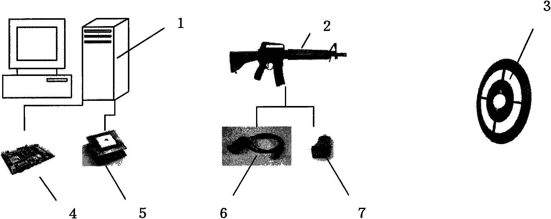
[0035] Such as figure 1 As shown, a schematic diagram of the composition of the shooting auxiliary training system of the present invention.

[0036] The shooting auxiliary training system comprises computer 1, gun 2, target 3, wireless video capture card 4, wireless trigger receiving device 5 and wireless miniature camera 6 and wireless trigger (trigger) 7; Wireless miniature camera is contained on the gun, wireless miniature camera Camera and gun aim at the same point; wireless video capture card and wireless trigger receiving device are installed in the computer; wherein: the captured image signal sent by the wireless miniature camera is received by the wireless video capture card, and the wireless trigger signal (trigger) signal) is received by the wireless trigger receiving device.

[0037] The computer 1 also includes image processing software and shooting au...


PUM


Abstract

The invention relates to a shooting auxiliary training system and image-based bulls eye positioning method. The system mainly comprises a computer, a gun, a target, a wireless video capture card, a wireless trigger receiving device, a wireless micro camera and a wireless trigger. The method is characterized in that: (1) the up and down and the left and right of an image shot when the center of the camera aims at the center of a shooting object are symmetrical about the aiming point of the center of the camera; (2) when a shooter holds the gun and aims at the center of the target, the center of the image shot by the camera is coincided with the center of the target image; (3) the image is shot by the camera, and the contact ratio of the center of the target image and the central position of the image is processed by and image processing software in the computer, so as to determine the ring number aimed by the shooter at the moment. The system has no special requirement on the target, requires no ball firing and has simple device and low cost; the whole shooting process can be monitored, replayed and analyzed, and the technical parameters of the shooter can be analyzed by a path formed by the aiming point in the shooting process.

Description

1. Technical field [0001] The invention belongs to the technical field of sports equipment, and mainly relates to a shooting auxiliary training system and a method for locating a bull's-eye based on an image. 2. Background technology [0002] At present, shooting training systems at home and abroad, such as Finland's Noptel, consist of laser emitting device guns, targets, and photoelectric receiving target array systems. The main disadvantages are: a), complex equipment, and large rotation errors. Improvements have been made. The photoelectric receiving system has been changed to reflective receiving. The receiving part is installed on the gun-mounted part, forming a double-tube system with the laser emitting system, which reduces the rotation error, but increases the weight of the gun. The photoelectric unit weighs 85g, and the additional weight 30-50g. b) The gun-mounted part has a transmission cable several meters long, and the weight of the cable is 40g / m. The additiona...

Claims


Application Information

Patent Timeline
Patent Type & Authority Applications(China)
IPC IPC(8): F41A33/00
Inventor 李德玉陈红星梁吉业霍浩
Owner SHANXI UNIV
Why Eureka
Try Eureka