

Computer terminal display system and display method for zoom lens target ranging
A computer terminal, zoom lens technology, applied in the direction of program control, installation, optics, etc. in the sequence/logic controller
- Summary
- Abstract
- Description
- Claims
- Application Information
AI Technical Summary
Problems solved by technology
Method used
Image

Examples
Embodiment Construction
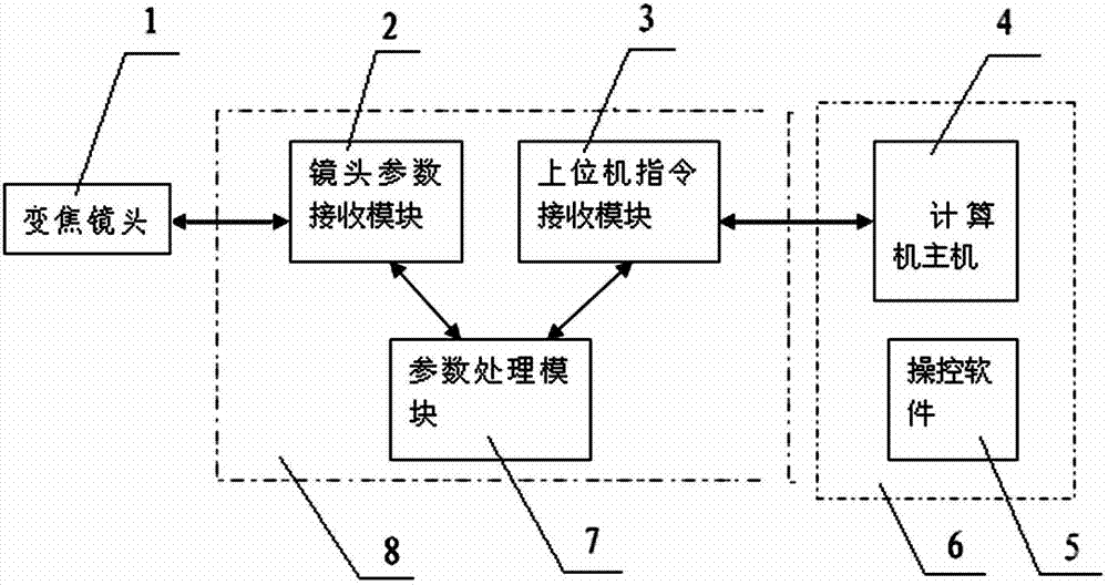
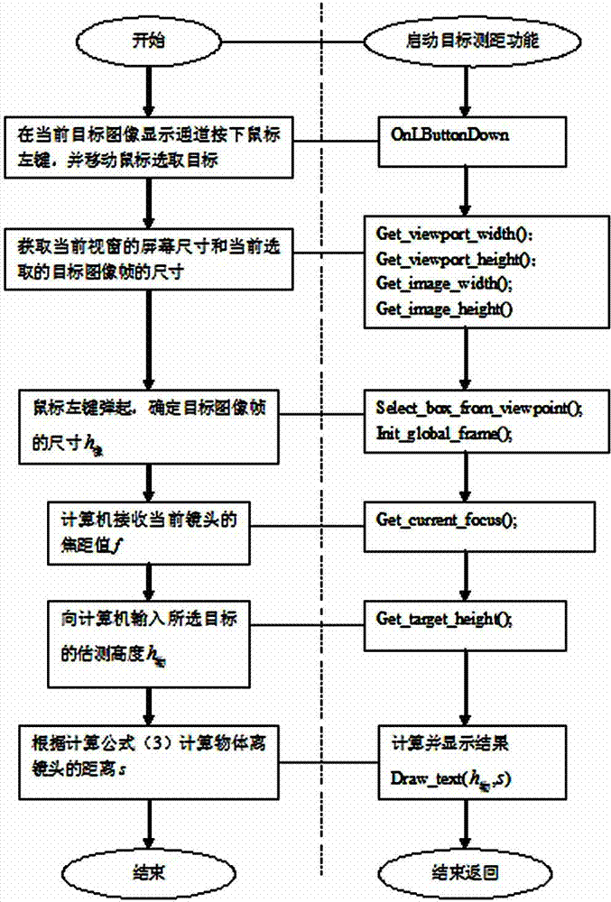
[0012] Such as figure 1 The computer terminal system for measuring the target range of the zoom lens has a zoom lens 1, the zoom lens 1 is connected to a lens parameter feedback control system 8, and the output of the lens parameter feedback control system 8 is connected to the computer display terminal system 6, wherein the lens parameter feedback control system 8 is composed of lens parameter receiving module 2, parameter processing module 7, and host computer command receiving module 3. Lens parameter receiving module 2 is connected to parameter processing module 7, parameter processing module 7 is connected to host computer command receiving module 3, and computer terminal display system 6 includes a computer mainframe 4, a display, and control software 5, and the upper computer instruction receiving module 3 is connected to the computer mainframe 4. Such as image 3 The computer terminal display method of the shown zoom lens target distance measurement is realized by th...
PUM
 Abstract
Description
Claims
Application Information