Electronic diopsimeter with functions of eyeball tracking and refraction compensation
What is AI technical title?
AI technical title is built by Patsnap AI team. It summarizes the technical point description of the patent document.
An eye tracking and perimetry technology, applied in the field of medical devices, can solve the problems of no automatic compensation for refractive error, narrowing sensitivity, and diffuse decrease in visual field sensitivity
Active Publication Date: 2009-12-16
EYE & ENT HOSPITAL SHANGHAI MEDICAL SCHOOL FUDAN UNIV
View PDF4 Cites 5 Cited by
Summary
Abstract
Description
Claims
Application Information
AI Technical Summary
This helps you quickly interpret patents by identifying the three key elements:
Problems solved by technology
Method used
Benefits of technology
Problems solved by technology
Although the Octopus Perimeter also monitors the position of the eyeball, it is a passive process. After the position of the pupil of the eyeball deviates from a certain range, the inspection procedure will stop automatically, and the technician needs to readjust before continuing the inspection.
[0006] 3. There is no automatic compensation function for refractive error: spatial visual field sensitivity is related to refraction. Refractive error can cause a diffuse decrease in visual field sensitivity and affect the judgment of visual field inspection results. At present, perimetry requires wearing frame glasses to correct refractive error. Correction of light errors, due to the influence of factors such as the size and shape of the frame glasses, the shape of the peripheral lenses, etc., after wearing glasses, the peripheral vision will be artificially asymmetrical and the surrounding area will be reduced or the sensitivity will be reduced, resulting in pseudo-defects of the peripheral vision
However, this perimetry does not have the function of automatically compensating for refractive errors; and it does not require the housing to be closed, so that the vision screen will communicate with the outside world, or one-way perspective glass needs to be installed, which is not as good as the perimetry of the present invention to directly control the peeping channel (51) opening size is economical
Method used
Image
Click on the blue label to locate the original text in one second.
Reading with bidirectional positioning of images and text.
Examples
Embodiment 1
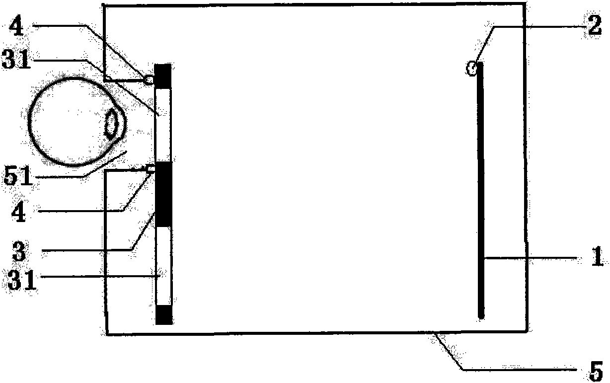
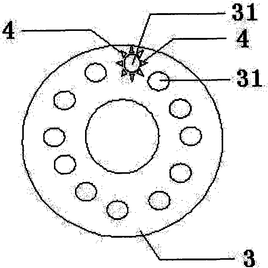
[0046] The structure of embodiment 1 electronic perimetry
[0047] The structure of an exemplary electronic perimetry is as Figure 1-2 As shown, it includes a housing 5 and a flat electronic vision screen 1. It is characterized in that the housing 5 has a cylindrical peeping channel 51, and the circular opening of the peeping channel 51 enables the subject to watch the housing from the outside of the housing 5. 5 inside; Peep channel 51 cylinder side circumference is equidistantly installed with 8 infrared lighting lamps 4 for emitting infrared rays to the subject's eyeball; peep channel (51) is connected with refractive correction system 3 inside, thereby sealing the shell Inside the body 5; the refractive correction system 3 is a turntable, on which 12 refractive correction aspheric lenses 31 are equidistantly distributed, wherein the correction degrees of the 12 refractive correction lenses (31) are respectively +6, +5, +4, +3, +2, +1, 0, -1, -2, -3, -4, and -5, so that the...
Embodiment 2
[0048] Example 2 Quantitatively evaluate the degree of cooperation of the subject
[0049] When testing the field of vision, the subject's eyes always fixate on the fixation point on the flat electronic vision screen 1 and look at the visual mark with peripheral vision, and adjust the refractive correction system 3 so that the subject can clearly see the visual mark on the electronic screen. Then, after the calculation system selects the three marker points in the eyeball of the subject, when the spatial coordinates are (S x , S y , 0) when the position S displays the visual mark, record the coordinates of the positions A, B, and C of the three mark points: A(A x , A y , A z ); B(B x , B y , B z ); C(C x , C y , C 2 ,);
[0050] Then, in the actual space coordinates are (S 1x0 , S 1y0 , 0) at position S 0 When the visual target is displayed, record the position A of the three marked points after displacement 1 , B 1 、C 1 Coordinates: A 1 ( A z1 ); B 1 (B ...
PUM
Abstract
The invention relates to an electronic diopsimeter with the functions of eyeball tracking and refraction compensation, which comprises a shell and a plane electronic visual field screen, wherein the shell is provided with a cylindrical peeping channel; the cylindrical lateral surface of the peeing channel is provided with an infrared illuminating lamp for emitting infrared rays to the eyeball of a subject; the inside of the peeping channel is connected with a refractive errorcorrection system so as to close the inside of the shell; the refractive errorcorrection system is provided with a non-spherical aspheric surface lens with refractive error correction; and an infrared camera for shooting the infrared ray reflected by the eyeball of the subject is also arranged in the shell. The electronic diopsimeter has the advantages of shell closure, eye ball tracking, refractive error correction and the like so that the accuracy is high. Besides, the invention also relates to a method for quantizing and evaluating the cooperation degree of the subject.
Description
technical field [0001] The invention belongs to the field of medical equipment, and relates to an ophthalmic visual field inspection device, which has the functions of eyeball tracking and refractive compensation, so it is accurate and reliable. In addition, the present invention also relates to a method for quantitatively evaluating a subject's cooperation degree by using the electronic perimetry. Background technique [0002] Visual field examination is the most basic examination in ophthalmology and the main basis for early diagnosis of glaucoma and optic neuropathy. With the application of computer technology in medicine in the 1980s, manual arc perimetry and plane perimetry have been replaced by computer-assisted automatic perimetry. These automated perimetry no longer depend on the skill of the perimetry technician and are simpler to operate, but still entirely dependent on patient subjectivity. [0003] At present, the perimetry in the world mainly includes the prod...
Claims
Application Information
Patent Timeline
Application Date:The date an application was filed.
Publication Date:The date a patent or application was officially published.
First Publication Date:The earliest publication date of a patent with the same application number.
Issue Date:Publication date of the patent grant document.
PCT Entry Date:The Entry date of PCT National Phase.
Estimated Expiry Date:The statutory expiry date of a patent right according to the Patent Law, and it is the longest term of protection that the patent right can achieve without the termination of the patent right due to other reasons(Term extension factor has been taken into account ).
Invalid Date:Actual expiry date is based on effective date or publication date of legal transaction data of invalid patent.
Patent Type & AuthorityApplications(China)
IPC IPC(8): A61B3/024
Inventor孙兴怀吴良成贺极苍贺际明周行涛
OwnerEYE & ENT HOSPITAL SHANGHAI MEDICAL SCHOOL FUDAN UNIV

