Combined type hydraulic cylinder design capable of supplying positive and negative bending roller force

A hydraulic cylinder and combined technology, applied in fluid pressure actuating devices, metal rolling, metal rolling racks, etc., can solve the problems of complex hydraulic control system, multiple hydraulic cylinder interfaces, and multiple auxiliary pipelines, and achieve The effect of reducing hydraulic pipelines, reducing sealing links, reducing sealing links and leakage

Inactive Publication Date: 2011-02-09
CHINA NON-FERROUS METALS PROCESSING TECH CO LTD
View PDF0 Cites 0 Cited by
  • Summary
  • Abstract
  • Description
  • Claims
  • Application Information

AI Technical Summary

Problems solved by technology

[0003] At present, the hydraulic roll bending devices used in rolling mills generally have complex structures, many sealing links, many hydraulic cylinder interfaces, and many auxiliary pipelines, and the corresponding hydraulic control system is also relatively complicated.

Method used


Image

  • Combined type hydraulic cylinder design capable of supplying positive and negative bending roller force
  • Combined type hydraulic cylinder design capable of supplying positive and negative bending roller force
  • Combined type hydraulic cylinder design capable of supplying positive and negative bending roller force

Examples


Embodiment Construction

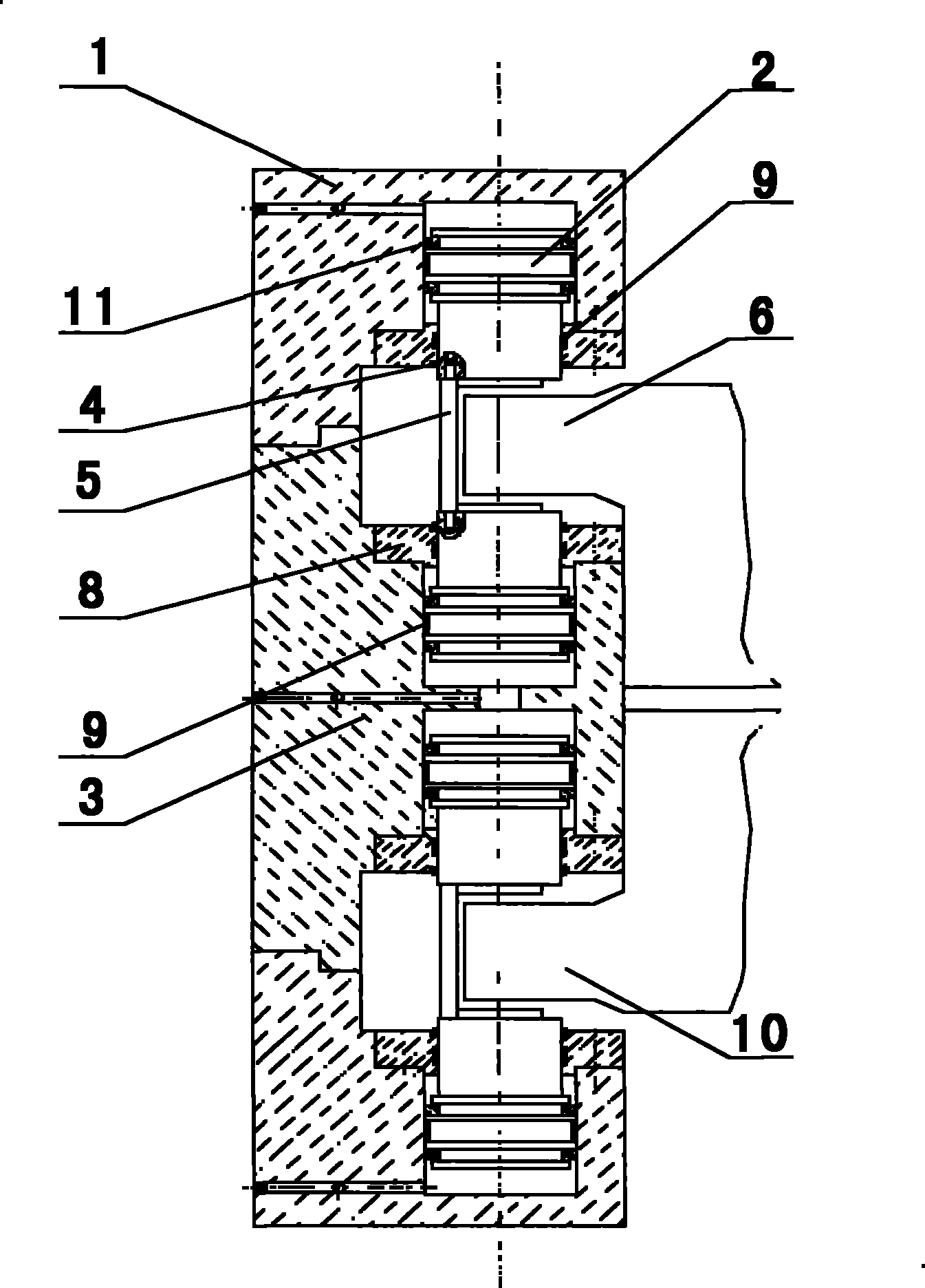
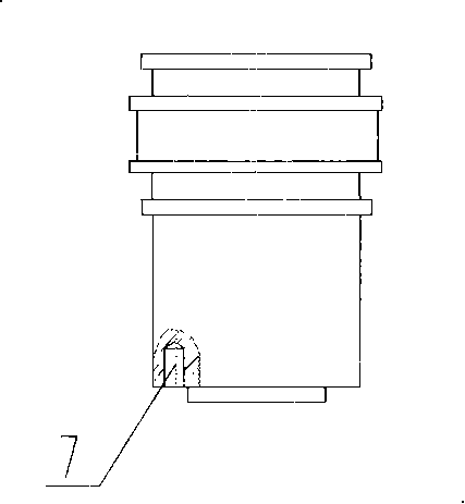
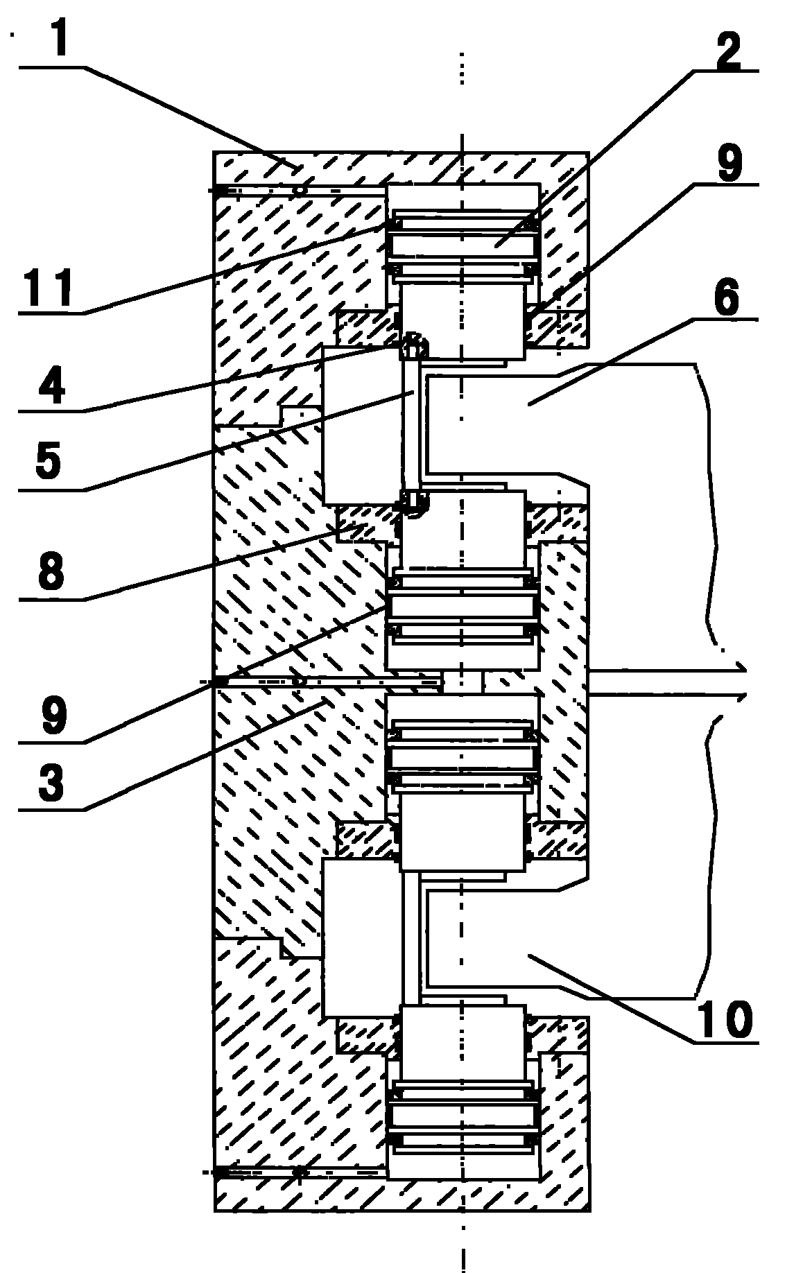
[0024] combine figure 1 , 2 , the design structure of the combined hydraulic cylinder that can provide positive and negative roll bending forces of the present invention consists of an end cylinder 1, a piston 2, an intermediate cylinder 3, a dustproof ring 4, a connecting rod 5, a flange cover 8, and a guide belt 9 , seal 11, wherein the end cylinder 1 is symmetrically installed on both ends of the middle cylinder 3, the end cylinder 1 and the middle cylinder 3 are provided with their own oil passages, the end cylinder 1 and the middle cylinder The same piston 2 is installed in the cylinder of the body 3, and the seal 11 is arranged on the piston 2, and one end surface of the piston 2 is designed with a counterbore 7, and each piston 2 installed in the cylinder is fixed by a flange cover 8 , the inner diameter of the flange cover 8 is designed with different annular grooves for installing the dust-proof ring 3 and the guide belt 9 respectively; two adjacent symmetrical and r...


PUM


Abstract

The invention relates to a combined type hydraulic cylinder design structure capable of supplying positive and negative bending roller force, comprising end cylinder bodies 1, pistons 2, a middle cylinder body 3, a dustproof ring 4, connecting rods 5, flange covers 8, a guide strap 9 and seal elements 11, wherein the end cylinder bodies are symmetrically installed at both ends of the middle cylinder body and provided with respective oil passages; the pistons are arranged in all cylinder barrels; the seal elements are configured on the pistons, and one end surface of each piston 2 is provided with a counter bore 7; all the pistons are fixed by the flange covers, and different annular concave grooves are arranged at the inner diameter of the flange covers and used for being respectively provided with the dustproof ring and the guide strap; the connecting rods are inserted into the counter bores of the two pistons which are adjacently, symmetrically and reversely installed; a space limited by the connecting rods can contain a lug boss of an upper roller bearing support 6 or a lower roller bearing support 10 so that the two pistons which are adjacently, symmetrically and reversely installed can supply positive and negative bending roller force; and the same pistons are installed in the cylinder barrel of the middle cylinder body back to back and share an oil passage of the middle cylinder body. The invention has simple structure and few seal steps and auxiliary pipelines and reduces the control degree.

Description

technical field [0001] The invention belongs to the technical field of metal calendering equipment, in particular to a combined hydraulic cylinder design capable of providing positive and negative roll bending forces. Background technique [0002] The hydraulic roll bending method has been widely used in modern metal strip mills to control the shape of the plate. The hydraulic roll bending method is to apply the pressure of the hydraulic cylinder to the roll neck to cause additional bending of the roll to compensate for the change of the roll gap under load. Get good shape. The hydraulic cylinder that provides the bending force is called the bending hydraulic cylinder, and the device that uses the bending cylinder to provide the bending force is called the hydraulic bending device. [0003] At present, the hydraulic roll bending devices used in rolling mills generally have complex structures, many sealing links, many hydraulic cylinder interfaces, and many auxiliary pipelin...

Claims


Application Information

Patent Timeline
Patent Type & Authority Patents(China)
IPC IPC(8): B21B31/32F15B15/02
Inventor 段宏波
Owner CHINA NON-FERROUS METALS PROCESSING TECH CO LTD
Why Eureka
Try Eureka