Fixed electrode of sliding welding machine

A technology of fixed electrode and sliding welding, applied in the direction of roller electrode welding, etc., can solve the problems of increased manufacturing cost, inconvenience, and high cost of use

Active Publication Date: 2009-12-16
凌德祥
View PDF0 Cites 0 Cited by
  • Summary
  • Abstract
  • Description
  • Claims
  • Application Information

AI Technical Summary

Problems solved by technology

In actual use, since the longitudinal ribs of the metal cage often rub against the rib guide groove, the rib guide groove is easily damaged. Once damaged, the outer surface of the fixed electrode must be reprocessed to make a new rib guide gro...

Method used


Image

  • Fixed electrode of sliding welding machine
  • Fixed electrode of sliding welding machine
  • Fixed electrode of sliding welding machine

Examples


Embodiment Construction

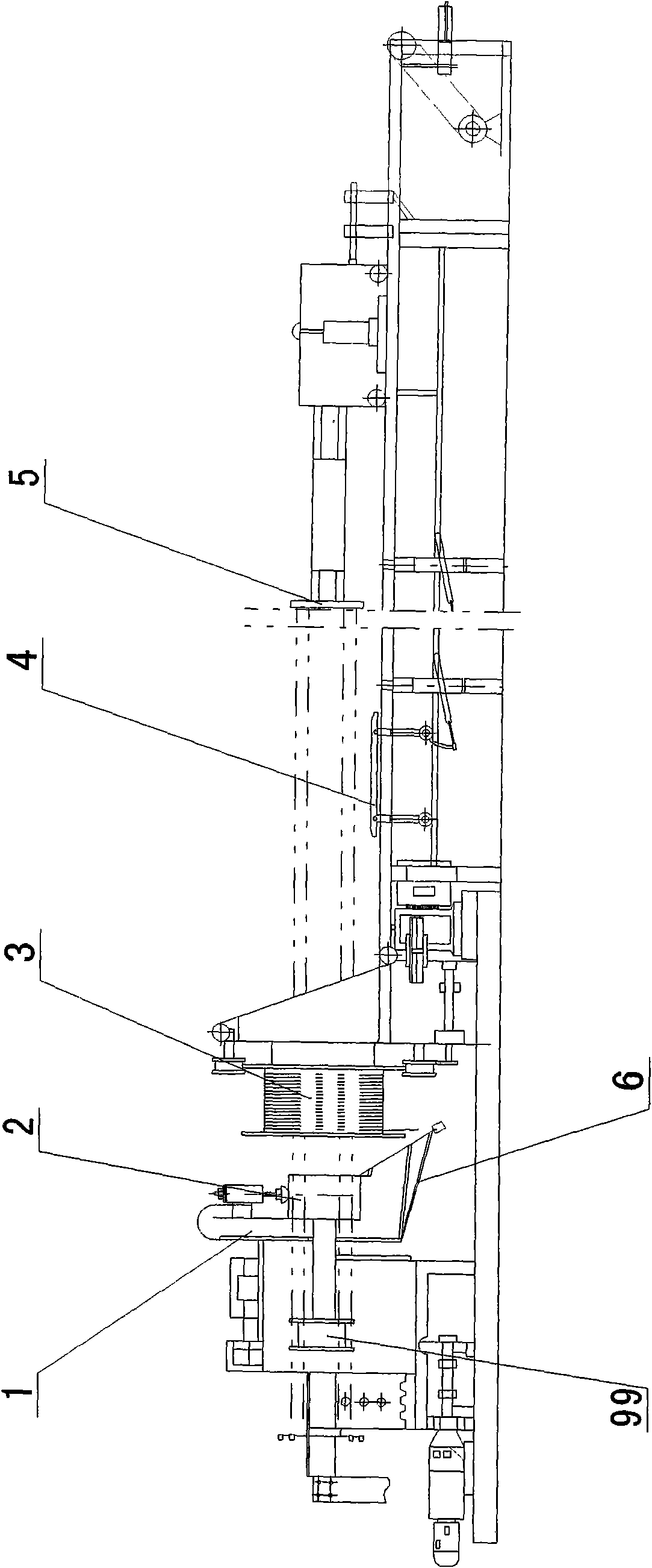
[0035] figure 1 A sliding welding device is shown, which includes an electrode wheel 1, a fixed electrode 2, a movable electrode, a longitudinal tendon traction disc 5, a fixed rib guide disc 99, a stirrup disc 3, a stirrup winding mechanism 6, and a metal cage transmission mechanism 4.

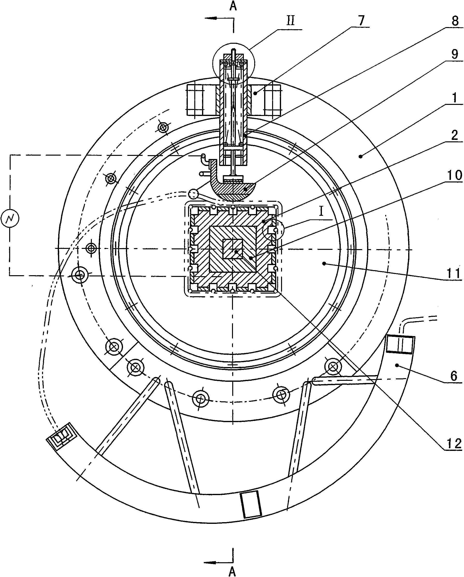
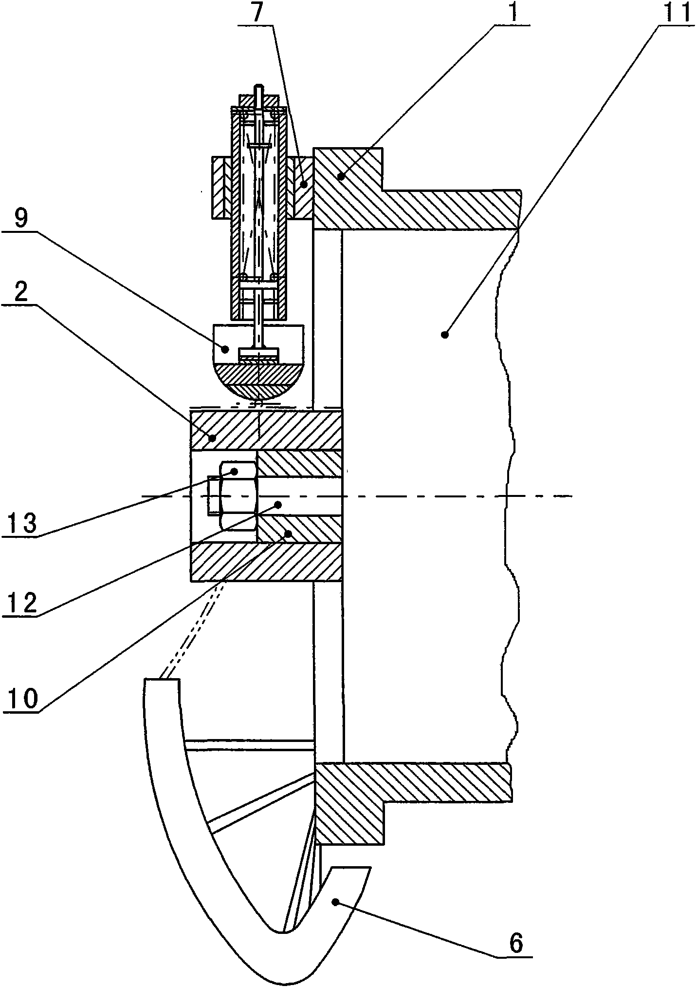
[0036] figure 2 Among them, the fixed electrode 2 is a square, and the outer surface of the fixed electrode 2 is provided with a number of grooves along the axial direction. The movable electrode has elastic movement along the radial direction of the fixed electrode 2, circumferential movement along the center of the fixed electrode 2, The electrode body 9 sliding on the outer side of the stirrup. The electrode body 9 is at the contact point between a longitudinal rib and the stirrup in the middle of one side of the fixed electrode 2, and the electrode body 9 is at the lowest position. The electrode body 9, longitudinal rib, stirrup and fixed electrode 2 shown in the figure are in the lead ...


PUM


Abstract

The invention provides a fixed electrode of a sliding welding machine, wherein, the transverse section of the fixed electrode is a heterotype curved surface; the base body of the fixed electrode is installed with a plurality of guide rib tank bodies; the guide rib tank is arranged on the guide rib tank bodies. The depth of the guide rib tank is greater than a half of the diameter of the longitudinal bar and the optimal depth is about two thirds of the diameter of the longitudinal bar, thus ensuring that the longitudinal bar bulges a little above the back cut of the guide rib tank body, thus prolonging the service life of the fixed electrode and saving use cost. A plurality of insulation boards are installed fixedly on the outer side of the fixed electrode; the back cut surface of the guide rib tank body is flush with the outer surface of the insulation board or is lower than the outer surface of the insulation board; or the two sides of the back cut surface of the guide rib tank body are provided with platforms and the insulation boards are arranged on the platforms, thus shortening as possible the distance between the side of the back cut surface guide rib tank of the guide rib tank body and the guide rib tank body to effectively prevent the electrode body from contacting with the guide rib tank body and breaking over before contacting with the longitudinal bar; if then, a large number of discharging phenomena are generated and the energy consumption is reduced.

Description

Technical field: [0001] The invention relates to welding equipment, in particular to welding elongated metal cages formed by cross-welding of metal ribs, such as fixed electrodes in electrode parts of welding equipment such as reinforcement cages for concrete components. Background technique: [0002] The existing roll welding equipment for long metal cages, such as the welding equipment for steel cages for concrete pipe piles, is designed for concrete pipe piles. There are several grooves for guiding ribs, and the fixed electrodes are fixed on the bracket. In actual use, since the longitudinal ribs of the metal cage often rub against the rib guide groove, the rib guide groove is easily damaged. Once damaged, the outer surface of the fixed electrode must be reprocessed to make a new rib guide groove, which is expensive to use. inconvenient. Moreover, the wear resistance and hardness of the entire fixed electrode are required to be high, and it must be treated with wear res...

Claims


Application Information

Patent Timeline
IPC IPC(8): B23K11/06
Inventor 凌德祥
Owner 凌德祥
Why Eureka
Try Eureka