Refrigeration equipment and air distribution plate thereof

The technology of refrigeration equipment and distribution plate is applied in the field of refrigeration equipment and air volume distribution plate, which can solve the problems of complex box structure, complicated air duct installation process, and difficulty in accurate distribution of air volume, etc. Installation cost, the effect of easy modification

Active Publication Date: 2009-12-16
HAIER GRP CORP +1
View PDF0 Cites 24 Cited by
  • Summary
  • Abstract
  • Description
  • Claims
  • Application Information

AI Technical Summary

Problems solved by technology

[0003] The air duct structure of the current refrigerator refrigeration system is mainly composed of an intermediate cavity surrounded by various related components, which means that for the current air duct structure, not only a good seal between the relevant components is required, but also the formation of the relevant components The installation process of the air duct is also more complicated
[0004] In the case where the chambers in the refrigerator are arranged in a simple manner, for example, when the chambers are arranged up and down or left and right, it is very difficult to adopt the air duct structure of the prior art. Convenient, but when the chambers in the box are arranged in a complex manner, for example, there are chambers arranged up and down, and chambers arranged left and right, the use of the air duct structure of the prior art will make the structure of the box very complicated. , because the temperature of each room needs to be controlled separately, that is, it is necessary to configure the air volume for each room more accurately. However, in the existing air duct structure, the fan is installed in the evaporator room, and the cold air is directly blown to each air duct branch, which is very difficult. It is difficult to achieve a more accurate distribution of air volume

Method used


Image

  • Refrigeration equipment and air distribution plate thereof
  • Refrigeration equipment and air distribution plate thereof
  • Refrigeration equipment and air distribution plate thereof

Examples


Embodiment Construction

[0033] The refrigeration equipment of the preferred embodiment of the present invention will be described in detail below in conjunction with the accompanying drawings.

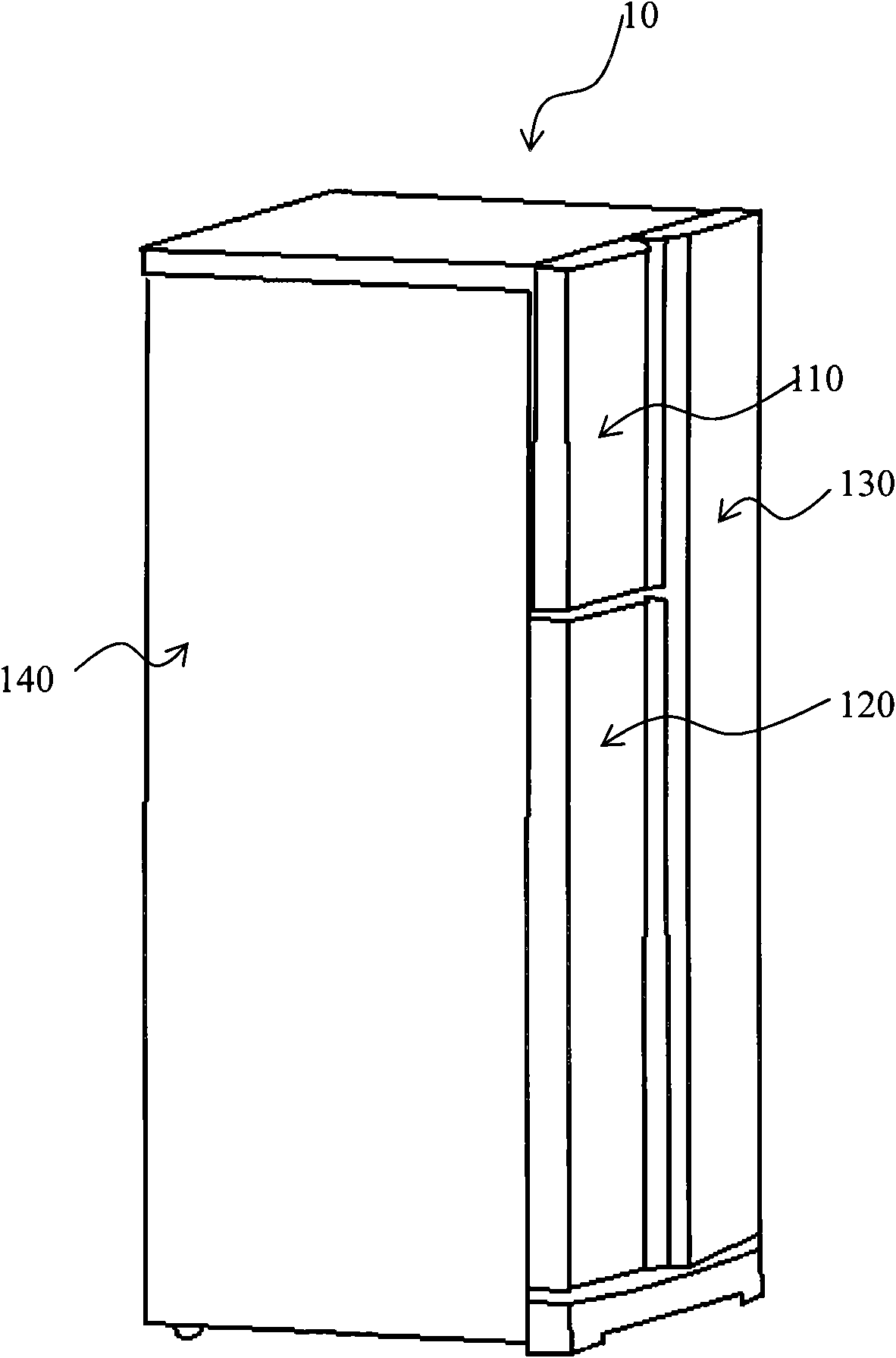
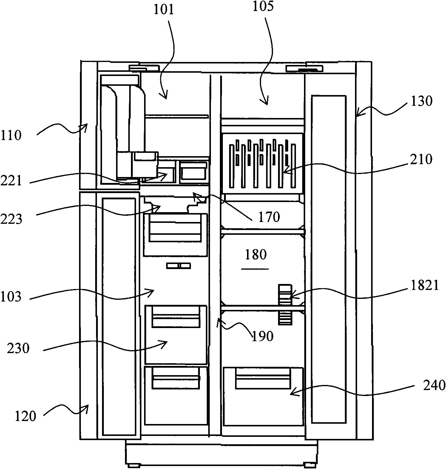
[0034] figure 1 A perspective view of a refrigeration device according to a preferred embodiment of the present invention is shown. Such as figure 1 As shown, the refrigeration equipment 10 is composed of a box body 140 and doors 110 , 120 , 130 installed on the box body 140 . The door 110 and the door 120 are located on the left side of the box body, and the door 130 is located on the right side of the box body. The door 110 closes the opening of the corresponding first refrigerating room 101, the door 120 closes the opening of the corresponding freezing room 103, and the door 130 closes the corresponding opening of the first refrigerating room 101. The opening of the second refrigerator compartment 105 .

[0035] In order to facilitate taking and placing items in the refrigeration equipment, while taking...


PUM


Abstract

The invention discloses refrigeration equipment. A liner of a case of the refrigeration equipment comprises an evaporator chamber, a plurality of refrigeration chambers and an air distribution plate, wherein an inner cavity of the air distribution plate is provided with an air passage and a fan, an air inlet of the air passage faces to the evaporator chamber, the fan is arranged at the air inlet of the air passage to absorb cool air inside the evaporator chamber into the air passage, and the air passage is provided with a plurality of air passage branches which are respectively led to each refrigeration chamber. The invention also discloses an air distribution plate comprising a front cover plate, a rear cover plate and a foam part, wherein the rear cover plate is buckled together with the front cover plate, and the foam part is clamped between the front cover plate and the rear cover plate and partially recessed to form the air passage which comprises the air inlet and the air passage branches. The air distribution plate of the refrigeration equipment simplifies the structure of the air passage, and the cool air led to each refrigeration chamber is uniformly distributed by the air distribution plate, therefore, the air inside each air passage branch can be accurately controlled.

Description

technical field [0001] The invention relates to a refrigerating device and an air volume distribution plate thereof, and the refrigerating device is especially suitable for a family living room. Background technique [0002] In modern families, refrigerators are commonly used due to the need to freeze or refrigerate items. With the continuous improvement of people's living standards, people's requirements for refrigerators are also getting higher and higher. Correspondingly, the design of refrigerators also tends to become more and more complicated, especially for the air duct design of refrigerator refrigeration systems. It is very difficult for those skilled in the art to simplify the air duct structure in the refrigerator space to adapt to various complex air duct designs and meet the design requirements of the refrigerator. [0003] The air duct structure of the current refrigerator refrigeration system is mainly composed of an intermediate cavity surrounded by various ...

Claims


Application Information

Patent Timeline
Patent Type & Authority Applications(China)
IPC IPC(8): F25D11/02F25D17/06
Inventor 慕志光毛庆波刘仁杰闫伟张林林
Owner HAIER GRP CORP
Why Eureka
Try Eureka