LED drive circuit suitable for controlled silicon light adjustment

一种LED驱动、驱动电路的技术,应用在电灯电路布置、光源、电光源等方向,能够解决不能够灵活控制、线路复杂、无法调节输出电压或者电流等问题

Active Publication Date: 2009-12-16
INVENTRONICS HANGZHOU
View PDF0 Cites 84 Cited by
  • Summary
  • Abstract
  • Description
  • Claims
  • Application Information

AI Technical Summary

Problems solved by technology

Since the LED power supply adopts high-efficiency, wide-range input voltage AC / DC high-frequency switching power supply, the traditional linear adjustment of input voltage or phase-controlled voltage regulation can no longer adjust the output voltage or current, and cannot realize the brightness adjustment of LED lights.
At present, there are many kinds of dimmable driving circuits: some use automatic timing dimming in the LED driver, that is, when the lamp is on for a certain period of time, the brightness will be lowered. This dimming circuit is affected by the built-in ambient brightness of the LED lamp. detection and timing control of the dimming circuit without the ability to flexibly control the
There is also a control circuit added to the LED driver to receive the wireless signal or power carrier signal sent by the controller, and use the signal to control the lighting brightness of the LED, but this method has high cost, complicated circuit and low reliability (refer to figure 1 )

Method used


Image

  • LED drive circuit suitable for controlled silicon light adjustment
  • LED drive circuit suitable for controlled silicon light adjustment
  • LED drive circuit suitable for controlled silicon light adjustment

Examples


Embodiment Construction

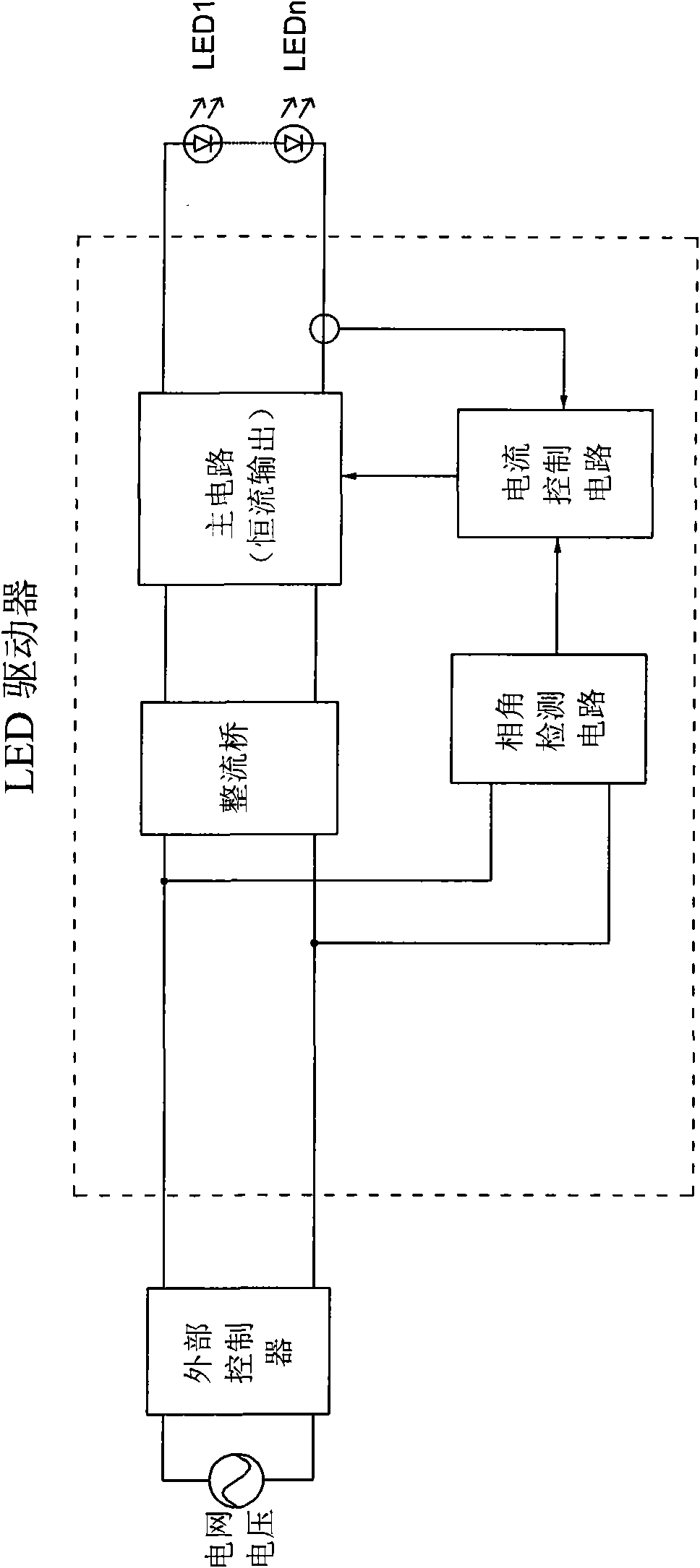
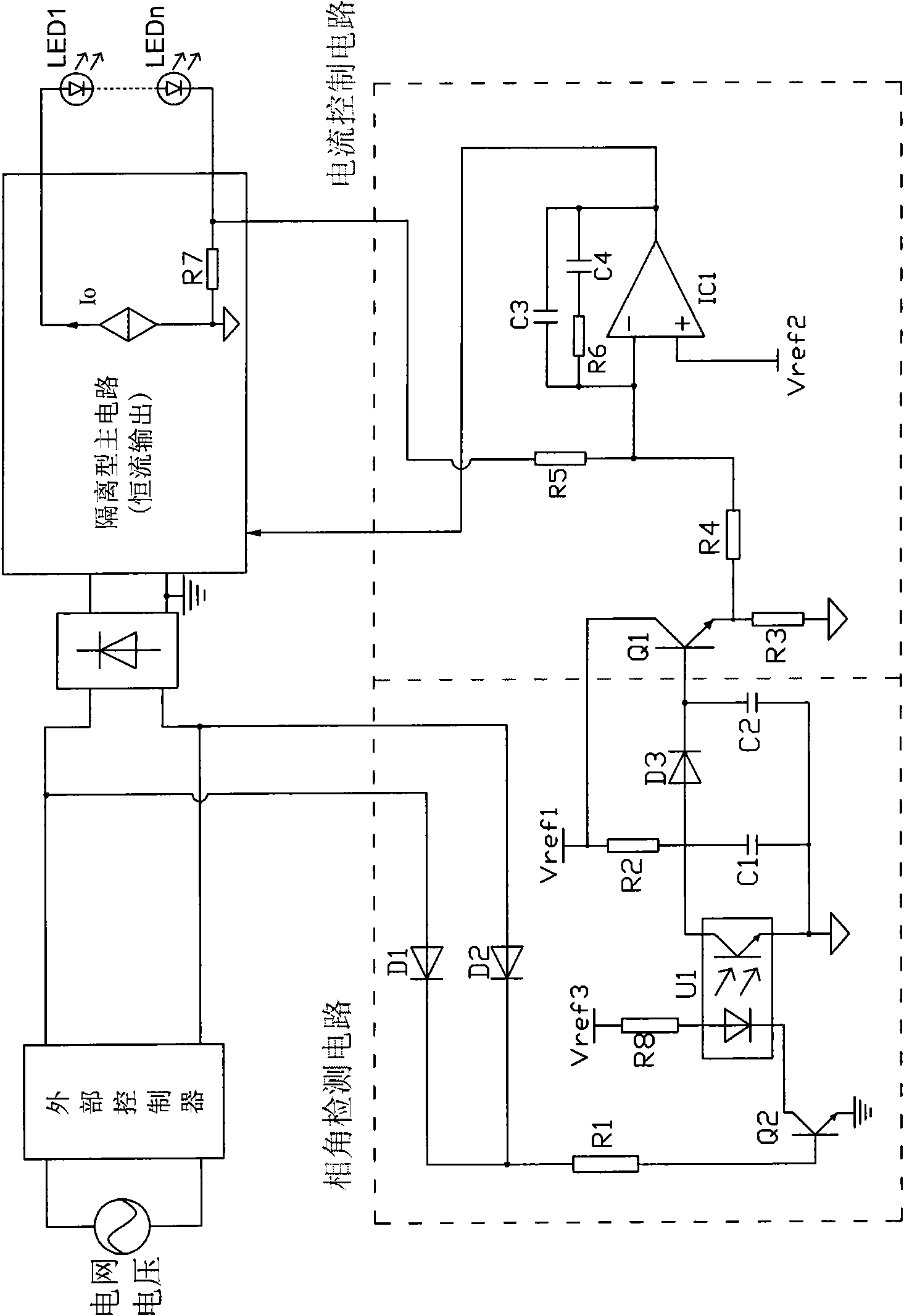
[0026] refer to figure 2 According to the present invention, the LED driver circuit suitable for thyristor dimming includes an external controller and an LED driver, and the LED driver includes a rectifier bridge, a main circuit, a phase angle detection circuit and a current control circuit. refer to image 3 , the phase angle detection and current control circuit can be isolated, and the main circuit is an isolated constant current output. The grid voltage is the input of the external controller, and the output of the external controller is the input of the rectifier bridge and the phase angle detection circuit; the phase angle detection circuit includes a resistor R1, a resistor R2, a resistor R8, a capacitor C1, a capacitor C2, a diode D1, Diode D2, diode D3, triode Q2, photocoupler U1, the anode of diode D1 and the anode of diode D2 are respectively connected to the two output terminals of the external controller, and the cathode of diode D1 is connected to the cathode o...


PUM


Abstract

The invention discloses an LED drive circuit suitable for controlled silicon light adjustment. The circuit comprises an outer controller and an LED driver, and is characterized in that the LED driver comprises a rectifier bridge, a main circuit, a phase angle detection circuit and a current control circuit. The LED drive circuit detects the phase of the trigger angle of a thyristor through the phase angle detection circuit and the current control circuit, and controls the brightness of an LED lamp through phase change; when the trigger angle of the thyristor is minimum, the LED lamp is brightest; when the trigger angle of the thyristor increases, the sawtooth wave peak value of the detection circuit increases and a level signal rises; the current control circuit feeds back the change to the main circuit and the output current of the main circuit decreases to darken the LED lamp, and vice versa. The LED drive circuit has simple structure and extremely low cost, and can obtain ideal light adjustment effect without a complicated modulation-demodulation circuit or a wireless transmission and receiving device; therefore, the circuit is suitable for light adjustment circuits controlled by any controlled silicon.

Description

technical field [0001] The invention relates to an LED drive circuit suitable for dimming of silicon controlled rectifiers. Specifically, it should be suitable for SCR dimming, LED drive circuit that detects phase angle and controls current. Background technique [0002] With the increasing energy consumption, the requirements for energy saving are also getting higher and higher, and lighting electricity consumption is an important part of people's energy consumption. As an energy-saving and green lighting method, new LED lighting will replace traditional gas discharge lamps and incandescent lamps. LED has long service life, high luminous efficiency, and can save a lot of electric energy, and the driving and control method of LED is simple, which is convenient for flexible adjustment of luminous brightness, especially suitable for some applications where luminous brightness needs to be adjusted according to different situations, such as street lamps, squares, etc. For publ...

Claims


Application Information

Patent Timeline
Patent Type & Authority Applications(China)
IPC IPC(8): H05B37/00H05B37/02H02M7/217
CPCY02B20/347H02M3/33507Y02B20/346H05B33/0815H02M3/156Y02B20/383Y02B20/348H05B45/385Y02B20/30
Inventor 华桂潮吴新科姚晓莉葛良安
Owner INVENTRONICS HANGZHOU
Why Eureka
Try Eureka