

Treatment system, and treatment device
A processing device and auxiliary processing technology, applied in medical science, surgery, surgical forceps, etc., can solve problems such as adverse effects on living tissues
- Summary
- Abstract
- Description
- Claims
- Application Information
AI Technical Summary
Problems solved by technology
Method used
Image

Examples
no. 1 approach
[0104] will refer to Figures 1 to 5D The first embodiment will be described.
[0105] Here, as an example of the energy processing device, a linear bipolar electrosurgical device 12 that performs treatment through the abdominal wall, for example, will be described.
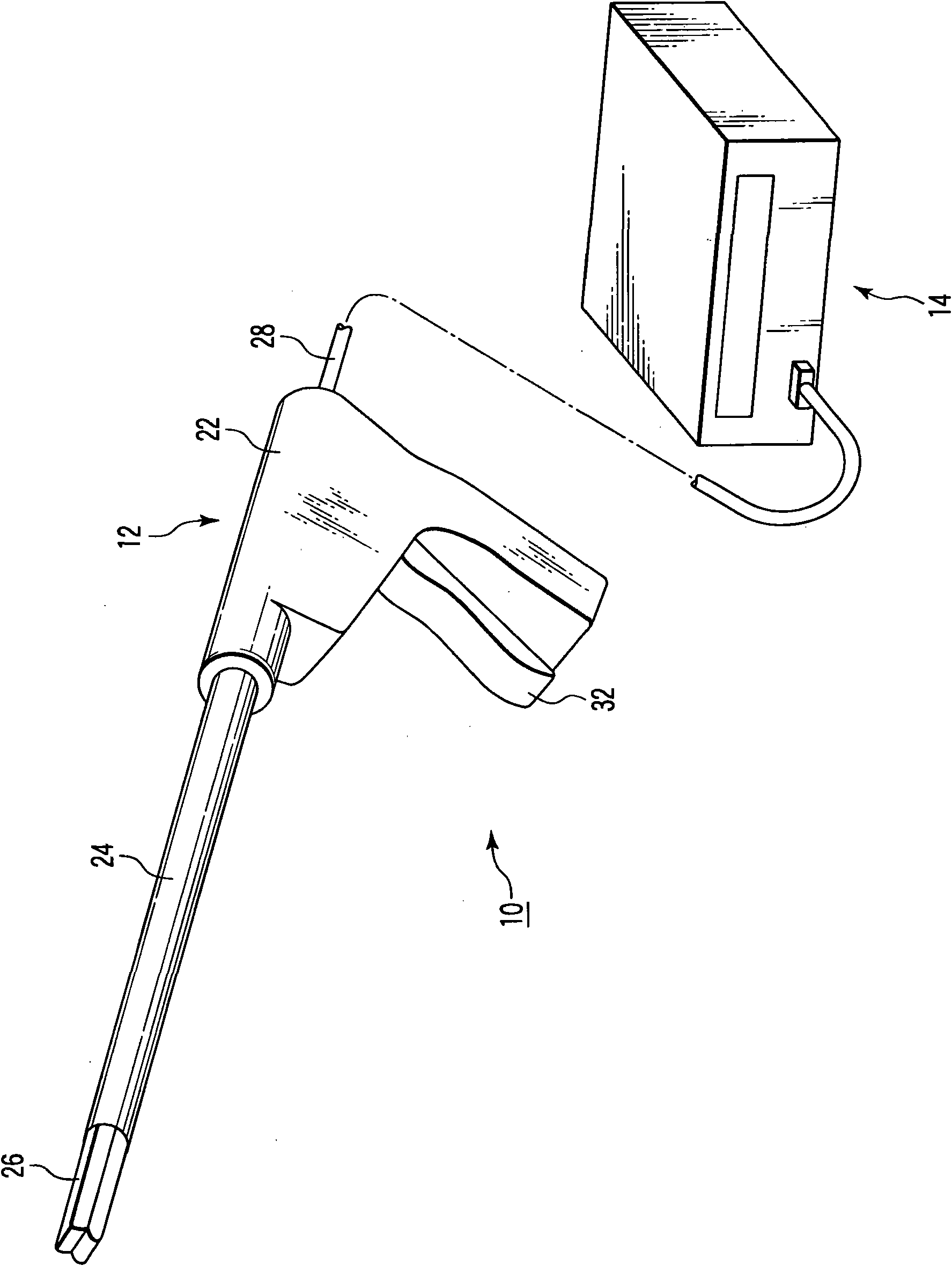
[0106] Such as figure 1 As shown, treatment system 10 includes an electrosurgical device (therapeutic treatment device) 12 and an energy source 14 .
[0107] The electrosurgical device 12 includes a handle 22 , a shaft 24 and an openable and closable retention region 26 . The handle 22 is connected to the energy source 14 via a cable 28 . The energy source 14 is connected to a foot switch and a hand switch (not shown). Therefore, the operator switches ON / OFF the energy supply from the energy source 14 to the electrosurgical device 12 by operating the foot switch and the manual switch.
[0108] The handle 22 is formed substantially in an L shape. A shaft 24 is provided at one end of the handle 22 . A cable ...
no. 2 approach
[0158] Next, refer to Figure 6A to Figure 7D A second embodiment will be described. This embodiment is a modification of the first embodiment, the same components as those explained in the first embodiment are denoted by the same reference numerals, and detailed descriptions of these same components are omitted.
[0159] Such as Figure 6A and Figure 6C As shown, on the outer side of the edge portion (barrier portion) 82a of the first holding portion 52, a pipe arrangement portion 96 is formed, which is provided with a pipe through which a cooling fluid such as gas or liquid (cooling water) flows (No. Two channels) 98. The duct 98 provided in the duct arrangement part 96 is formed in a cylindrical shape, for example. The outer peripheral surface of the duct 98 is provided in contact with an imaginary surface extending from the contact surface of the edge portion 82a. That is, a portion of the outer peripheral surface of the duct 98 along the axial direction is substanti...
no. 3 approach
[0184] Next, refer to Figure 8A to Figure 8C A third embodiment will be described. This embodiment is a modification of the first embodiment, the same components as those in the first embodiment are denoted by the same reference numerals, and detailed descriptions of these same components are omitted.
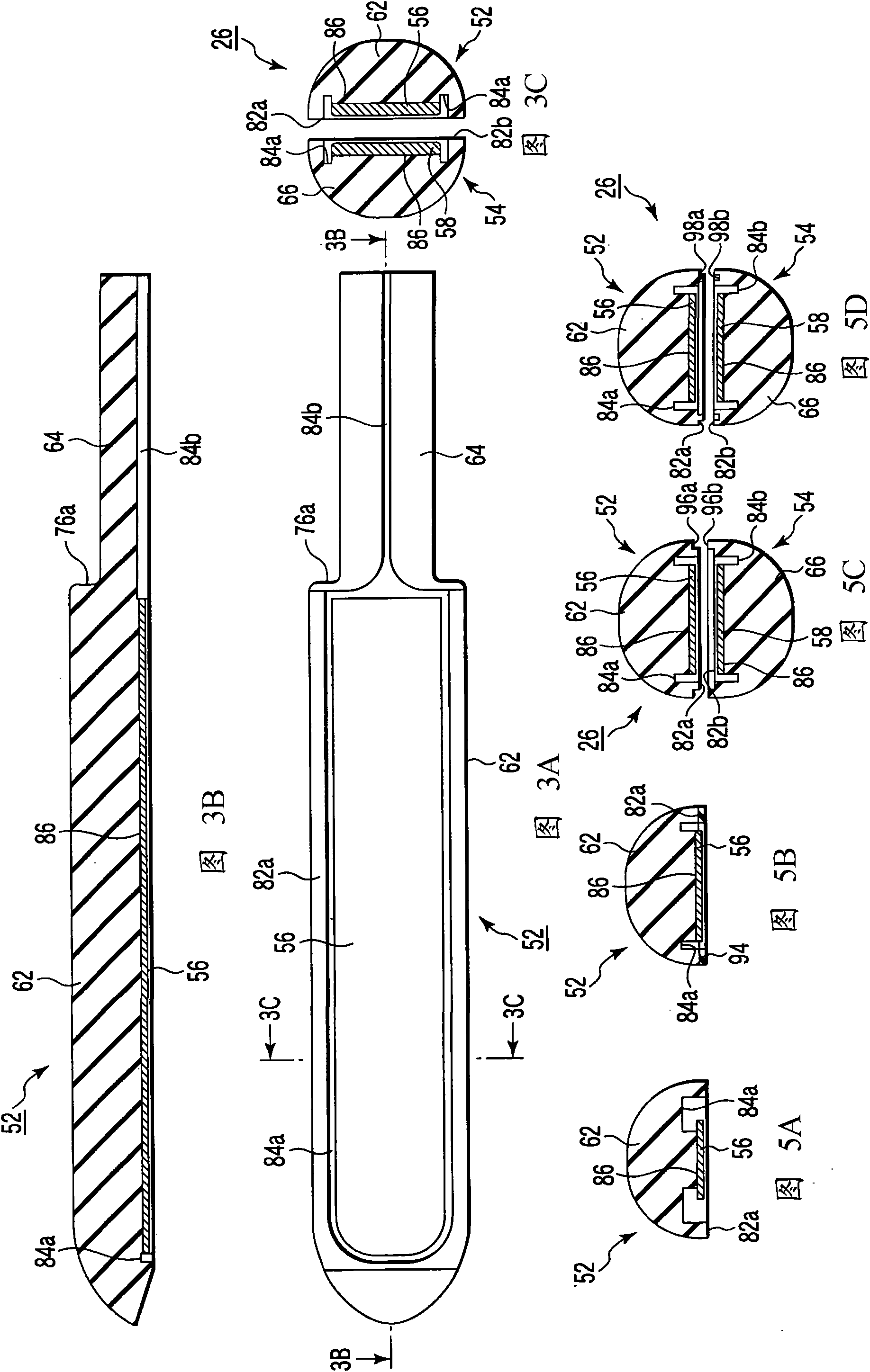
[0185] Such as Figure 8C As shown, the first fluid drainage groove 84a has been removed from the edge portion 82a of the main body 62 of the first retaining portion 52 (see Figure 3A to Figure 3C ). Furthermore, in the edge portion 82a of the main body 62 of the first holding portion 52, an electrode arrangement portion 86 serving as a base on which the first high-frequency electrode 56 is provided is formed adjacent to the edge portion 82a. The electrode arrangement portion 86 is provided with a first fluid discharge groove 112 a along the axial direction of the main body 62 . Such as Figure 8B and Figure 8C As shown, the first fluid discharge groove 112a is formed ...
PUM
 Abstract
Description
Claims
Application Information