Electric control braking device

A technology of braking device and electric control, applied in the direction of electromechanical device, electric braking system, electric vehicle, etc.

Inactive Publication Date: 2009-12-16
RENAULT SA
View PDF1 Cites 18 Cited by
  • Summary
  • Abstract
  • Description
  • Claims
  • Application Information

AI Technical Summary

Problems solved by technology

On the contrary, the use of Terfenol-D with good properties brings integration and cost problems

Method used


Image

  • Electric control braking device
  • Electric control braking device
  • Electric control braking device

Examples


Embodiment Construction

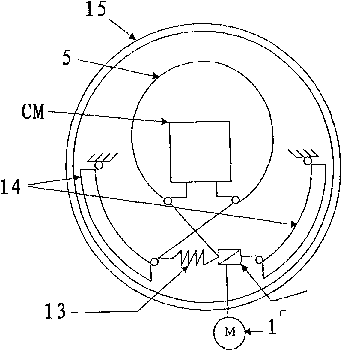
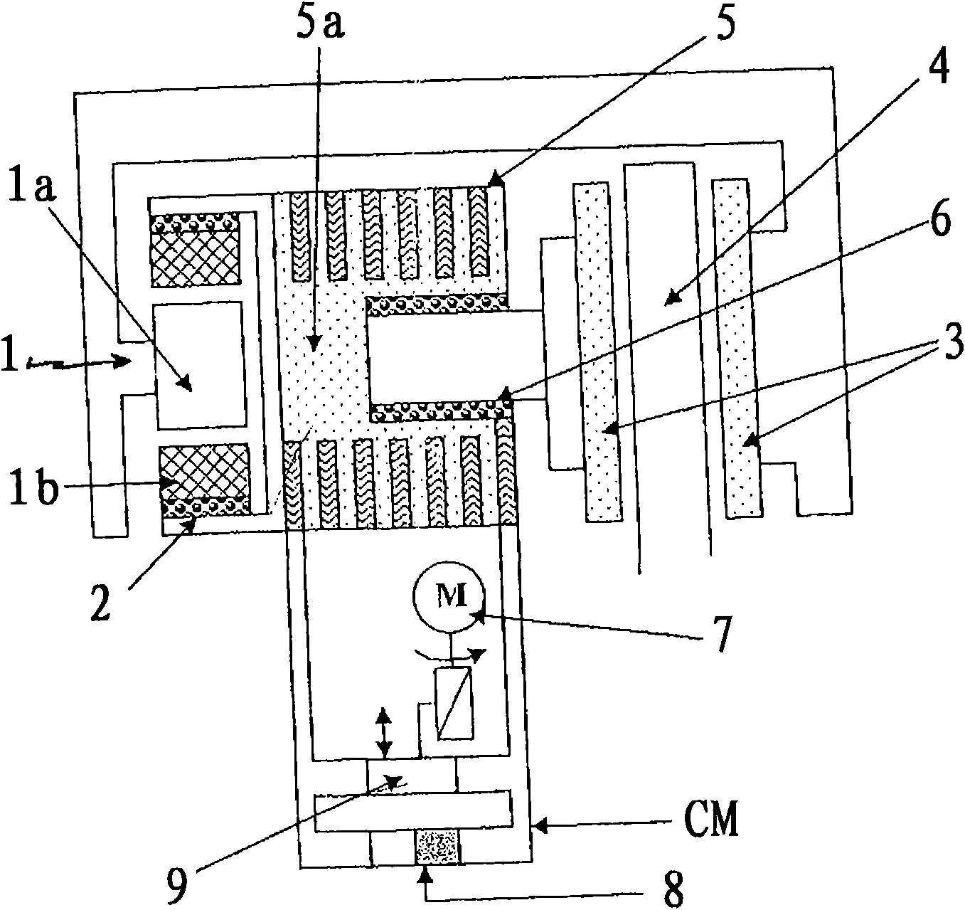
[0025] In a known manner, as shown schematically in the attached drawing, this electrically controlled braking device comprises an electric motor 1 mounted in combination with, for example, a ball screw 2 to allow Rapid movement of multiple brake pads 3 coordinated by elements. In combination with the electric motor 1 , the device comprises a magnetostrictive actuator 5 capable of exerting a force on the pad 3 against the disc 4 or drum. In these figures, 1 a designates the stator of an electric motor or other moving actuator, while reference 1 b designates the rotor of the actuator 1 , which is mounted in combination with a ball screw 2 .

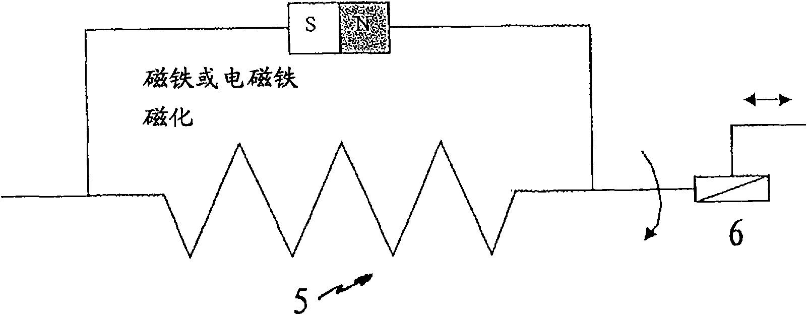
[0026] According to a characteristic of the invention, the magnetostrictive actuator comprises a winding 5 mounted on a core 5a (serving as a guide). This guide 5a is also installed in combination with, for example, a ball screw 6 or other elements. As shown in the figures, the winding 5 has gaps between each turn in order to limit short...


PUM


Abstract

The invention relates to a braking device that comprises an electric motor (1) capable of acting with the means (2) for the quick movement of the pads (3) into contact with a disk (4) or a drum, and a magnetostrictive actuator capable of generating a clamping force on the pads and against the disk or the drum. The magnetostrictive actuator comprises at least one winding (5) of a magnetic material on a holder (5a).

Description

technical field [0001] The present invention generally relates to the braking technology industry, in particular to an electric control braking device. Background technique [0002] Usually, in a known manner, such braking uses at least one actuator (most often in the form of an electric motor), which must on the one hand allow a rapid movement so that, for example, the two pads and the brake disc or the drum, while on the other hand allows the application of a considerable force to clamp the pads against the surface of the disc or drum, thereby generating a braking torque. It is not sufficient to use a single actuator to perform both functions of movement and clamping. This is why these known solutions generally use an electric motor and a ball screw to ensure the rapid movement function and a magnetostrictive actuator to perform the clamping force function. [0003] With this solution, the motor can be designed for weak power, which is necessary and limited to the rapid ...

Claims


Application Information

Patent Timeline
Patent Type & Authority Applications(China)
IPC IPC(8): F16D65/21F16D65/18
CPCF16D2125/40H02K7/06H02K7/1021F16D2121/24Y02T10/641F16D2121/28H01L41/12B60L7/003B60L2200/26Y02T10/64H10N35/00
Inventor S·盖伊
Owner RENAULT SA
Why Eureka
Try Eureka