
Gear synchronous driving mechanism

A technology of synchronous transmission and coaxial transmission, which is applied in the direction of gear transmission, transmission, belt/chain/gear, etc., which can solve the problems of high production cost and large size, prolong service life, improve assembly accuracy and transmission accuracy , Simple and reliable action

Inactive Publication Date: 2009-12-23
无锡市金龙人造毛皮机械有限公司
View PDF0 Cites 1 Cited by
  • Summary
  • Abstract
  • Description
  • Claims
  • Application Information

AI Technical Summary

Problems solved by technology

[0003] The purpose of the present invention is to provide a gear synchronous transmission mechanism, which solves the problems of large size and high production cost in the way of central spindle transmission in large circular knitting machine textile machinery

Method used


Image

  • Gear synchronous driving mechanism

Examples


Embodiment Construction

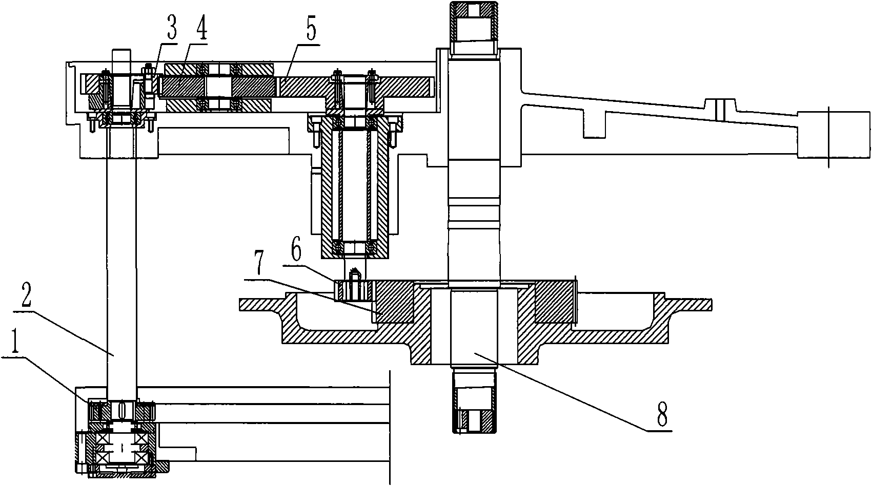
[0011] Such as figure 1 As shown, the gear synchronous transmission mechanism described in the embodiment of the present invention includes a central main shaft 8, on which a needle cover gear 7 is installed, the needle cover gear 7 is connected with the upper transmission pinion 6, and the upper transmission pinion 6 Coaxial transmission with the upper transmission gear 5, the upper transmission gear 5 meshes with the adjustment gear 3 through a bridge gear 4, the adjustment gear 3 is connected with the transmission gear 1 through the transmission shaft 2, and the transmission gear 1 is connected with external power. In this way, the external power is transmitted to the transmission shaft 2 through the transmission gear 1, then through the adjustment gear 3, through the bridge gear 4, it is transmitted to the upper transmission large gear 5 and the upper transmission pinion 6, and finally the upper needle cover gear 7 is transmitted to the center. Axis 8. Such a design can p...


PUM


Abstract

The invention relates to a gear synchronous driving mechanism which comprises a central main shaft, wherein a needle cover gear is arranged on the central main shaft and connected with an upper driving pinion, the upper driving pinion and an upper driving gearwheel are driven coaxially, the upper driving gearwheel is meshed with an adjusting gear through an intermediate gear, the adjusting gear is connected with a driving gear through a driving shaft, and the driving gear is connected with external power. The gear synchronous driving mechanism has the beneficial effects: the fine tuning of the driving gear can be realized, the action is simple and reliable, the adjustment is free and not limited by shaft shoulders, the assembling precision and the driving precision of the driving gear are improved, and the service life of the driving gear is prolonged.

Description

technical field [0001] The invention relates to a textile machine, in particular to a circular machine spindle transmission mechanism on the textile machine. Background technique [0002] At present, the commonly used circular knitting machine of textile machinery adopts the mode of central spindle transmission, which has a large size and high production cost. The present invention improves on this problem, and changes the drive shaft from the central main shaft to the side transmission shaft, and the central main shaft is used as the driven shaft. After such improvement, the size of the whole machine can be reduced and the manufacturing cost can be saved. Contents of the invention [0003] The purpose of the present invention is to provide a gear synchronous transmission mechanism, which solves the problems of large size and high production cost in the way of central spindle transmission in large circular knitting machine textile machinery. [0004] The purpose of the pr...

Claims


Application Information

Patent Timeline
IPC IPC(8): F16H1/20D03D51/00D04B35/00
Inventor 吴敏良
Owner 无锡市金龙人造毛皮机械有限公司
Learn More