Pneumatic gate valve for welding type high-temperature resistant bellows

A welded, bellows technology, applied in the field of pneumatic gate valves, to achieve good anti-corrosion and anti-friction performance, good anti-friction performance, and improve the safety of factory equipment

Inactive Publication Date: 2009-12-23
SHANGHAI HAIXING VALVE FACTORY
View PDF0 Cites 1 Cited by
  • Summary
  • Abstract
  • Description
  • Claims
  • Application Information

AI Technical Summary

Problems solved by technology

[0003] In order to solve the technical problem that the gate valve is forced to seal, when the valve is closed, pressure must be applied to the gate to force the sealing surface not to leak. This invention provides a pneumatic welded high temperature resistant bellows gate valve.

Method used


Image

  • Pneumatic gate valve for welding type high-temperature resistant bellows

Examples


Embodiment Construction

[0007] The present invention will be further described below in conjunction with the accompanying drawings and embodiments.

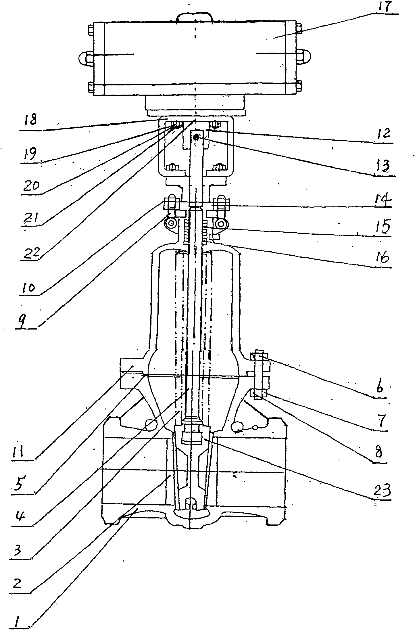
[0008] In the figure: 1. Welded valve body, 2. Overlay welding Co-based hard alloy sealing ring, 3. Titanium-plated austenitic stainless steel bellows device, 4. Valve stem, 5. High temperature resistant gasket, 6. Bolt , 7. Spring washer, 8. Nut, 9. Jack screw, 10. Jack nut, 11. Valve cover, 12. Pneumatic head mandrel sleeve, 13. Cross bolt, 14. Packing gland, 15. Packing, 16 .Lower packing pad, 17. Pneumatic head device, 18. Pneumatic head device frame, 19. Bolt, 20. Spring washer, 21. Nut, 22. Pneumatic head mandrel, 23. Gate.

[0009] exist figure 1 In the shown example: the pneumatic head device 17 is mechanically connected with the pneumatic head device frame 18, the pneumatic head device frame 18 and the valve cover 11 are mechanically connected by bolts 19, spring washers 20, nuts 21, the pneumatic head mandrel 22 is connected with the valve st...


PUM


Abstract

The invention relates to a pneumatic gate valve for welding type high-temperature resistant bellows, in particular to a pneumatic gate valve. The pneumatic gate valve comprises a welding type valve body, wherein a pneumatic head device is connected with a pneumatic head device frame; the pneumatic head device frame is mechanically connected with a valve cap through a bolt, a spring spacer and a nut; a pneumatic head mandrel and the upper side of a valve stem are mechanically connected with a pneumatic head mandrel sleeve through a cross-bolt; a Co-based hard alloy seal ring is arranged on the welding type valve body in a mode of surface welding; an adjustable mechanism of titanizing austenitic stainless steel bellows is connected between the lower side of the valve stem and the upper side of a gate plate; and a head part below the valve stem is connected with an adjustable mechanism of the gate plate so that the titanizing austenitic stainless steel bellows are driven to lift by a lifting rod of the valve stem. The pneumatic gate valve has the advantages of simple structure and convenient installation; the pneumatic head can be used for an automatic control pipeline; the dual sturdy and durable bellow is conveniently disassembled; the hermetical design for the dual sturdy and durable bellows ensures the zero leakage of the valve stem.

Description

Technical field: [0001] The invention relates to a pneumatic gate valve. Background technique: [0002] At present, in the known gate valve, the opening and closing part of the gate valve is a plug-shaped gate, the sealing surface is a plane or a conical surface, and the gate moves linearly along the center line of the fluid. The movement type of the valve stem has a lifting rod type. The gate valve is only suitable for full opening and full closing, and adjustment and throttling are not allowed. It is a forced sealing valve, so when the valve is closed, pressure must be applied to the gate to force the sealing surface not to leak. When the medium enters the valve from the bottom of the gate, the resistance that the operating force needs to overcome is the friction between the valve stem and the packing and the thrust generated by the pressure of the medium. The force to close the valve is greater than the force to open the valve, so the valve stem The diameter of the val...

Claims


Application Information

Patent Timeline
Patent Type & Authority Applications(China)
IPC IPC(8): F16K41/10F16K3/00F16K3/30F16K27/04F16K41/02F16K31/12
Inventor 季祝华
Owner SHANGHAI HAIXING VALVE FACTORY
Why Eureka
Try Eureka