Protective circuit for balanced circuit of power converter

A technology for power converters and balancing circuits, applied in the direction of adjusting electrical variables, converting DC power input to DC power output, instruments, etc., can solve problems such as damage, and achieve the effect of improving circuit reliability and product competitiveness.

Active Publication Date: 2012-12-05
VERTIV CORP
View PDF5 Cites 0 Cited by
  • Summary
  • Abstract
  • Description
  • Claims
  • Application Information

AI Technical Summary

Problems solved by technology

[0007] The disadvantage of this balance circuit for power converters is that the relationship between the input positive and negative bus voltages largely determines the current flowing through the switching tubes, and the control chip can only perform wave-by-wave current limiting protection for one switching tube. Make another switch tube in the circuit may flow a large current and cause damage

Method used


Image

  • Protective circuit for balanced circuit of power converter
  • Protective circuit for balanced circuit of power converter
  • Protective circuit for balanced circuit of power converter

Examples


Embodiment Construction

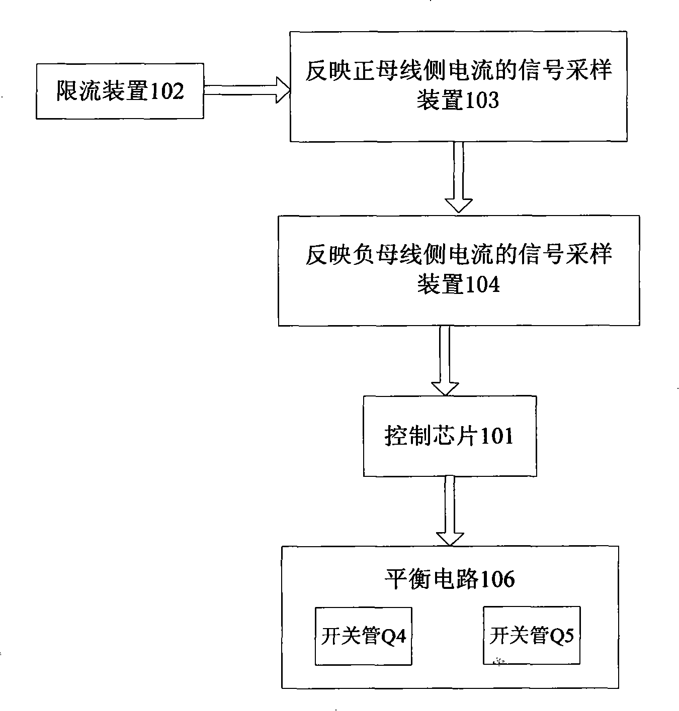
[0027] image 3 It is a circuit principle block diagram of the protection circuit for the balance circuit of the power converter of the present invention. Such as image 3 As shown, a protection circuit for a balance circuit of a power converter includes a control chip 101, a signal sampling device 103 reflecting the positive bus side current, a signal sampling device 104 reflecting the negative bus side current, and the reflecting positive The signal sampling device 103 of the bus side current is connected to limit the current limiting device 102 flowing through the current intensity of the switch tube in the balance circuit 106; the signal sampling device 104 reflecting the negative bus side current obtains the sampling signal reflecting the negative bus side current, and superimposes The sampling signal reflecting the positive bus side current and the sampling signal reflecting the negative bus side current generate a superimposed sampling signal, and the control chip 101 ...


PUM


Abstract

The invention relates to a protective circuit for a balanced circuit of a power converter, comprising a control chip, a signal sampling device reflecting the side current of a positive bus, a signal sampling device reflecting the current of a negative bus and a current-limiting device connected with the signal sampling device reflecting the side current of the positive bus to limit the intensity of current passing through a switch pipe of the balanced circuit, wherein the signal sampling device reflecting the current of the negative bus acquires a sampling signal reflecting the side current of the negative bus and overlays a sampling signal reflecting the side current of the positive bus and the sampling signal reflecting the side current of the negative bus to generate an overlaid sampling signal; and the control chip acquires the overlaid sampling signal from the signal sampling device reflecting the current of the negative bus and controls the on-off of the switch pipe of the balanced circuit according to the overlaid sampling signal. The protective circuit for the balanced circuit of the power converter can timely carry out wave by wave current-limiting protection on the switch pipe, thereby enhancing the reliability of circuits.

Description

technical field [0001] The present invention relates to a protection circuit, and more particularly, to a protection circuit for a balance circuit of a power converter. Background technique [0002] At present, in converters with medium and high power output (including DC / DC converters and AC / AC converters), the primary side series connection technology of two identical converters is generally used to expand the output power capacity. However, in the actual circuit, due to the inconsistent driving pulse width and inconsistent efficiency caused by the discreteness of the parameters of the two converters, the output power of the two converters will be unequal, resulting in unequal input voltages of the DC bus capacitors, that is, unbalanced. This situation is especially serious under light load. Therefore, someone proposed a balance circuit for a power converter to achieve voltage equalization among the various units in the converter, to stabilize the voltage of the bus capa...

Claims


Application Information

Patent Timeline
Patent Type & Authority Patents(China)
IPC IPC(8): H02M1/32H02M3/335
Inventor 肖学礼林清森陈勇兵
Owner VERTIV CORP
Why Eureka
Try Eureka