A Bilateral Feedback and Control DSR Architecture

A bilateral, control module technology, used in control/regulation systems, output power conversion devices, DC power input conversion to DC power output, etc., can solve problems such as poor dynamic response, poor feedback, and occupying space.

Active Publication Date: 2021-07-16
SHENZHEN YUANNENG ELECTRIC CO LTD
View PDF10 Cites 0 Cited by
  • Summary
  • Abstract
  • Description
  • Claims
  • Application Information

AI Technical Summary

Problems solved by technology

[0003] Usually, the SSR secondary side feedback architecture is required to feed back the output voltage and current, but the SSR architecture requires 431, optocoupler, voltage divider resistors and other devices to occupy space, and the conventional PSR cannot perform constant current and constant power switching. When the 18W fast charge adopts the constant current mode, 5V3A, 12V is still 3A, the power reaches 36W, the main control and transformer will be overloaded and the machine will explode; when using constant power mode, there is no problem at 12V1.5A, when the 4V output current will reach 4.5A and burn out synchronously ;
[0004] Exowatt's resonant square wave detection technology, such as Figure 8 In the position of ②, feedback is sent to the primary chip to change the voltage and current parameters. This process takes several MS or even dozens of MS, resulting in poor dynamic response;
[0005] PI's separate electromagnetic mutual inductance feedback, because its chip needs to span the primary and secondary stages, in many circuits, the primary pole needs to be separated from two boards, or the primary pole needs to be isolated, which is inconvenient to use;
[0006] Shenzhen Yuanneng Electric Applied, in such as Figure 8 It takes a certain amount of time to judge the position of ② in the RC damping step-down feedback, and it is not easy to feedback for the CCM continuous mode
[0007] In addition, for the PSR architecture, the secondary output voltage can only be captured after 2-3uS from the start of secondary demagnetization. When it is no-load, it usually demagnetizes. After the resonance is completed, it usually needs to be lightly turned on again every few mS or tens of mS. Detect the output voltage. If it is turned on frequently, it will cause the output voltage to float. This will increase the power consumption of the dummy load and reduce the efficiency. Therefore, the output is suddenly loaded during the no-load period, which will suddenly pull down the output voltage, and cannot be fed back in time. Primary, only the next light start can detect that the output voltage is not enough, so the dynamic response is poor

Method used


Image

  • A Bilateral Feedback and Control DSR Architecture
  • A Bilateral Feedback and Control DSR Architecture
  • A Bilateral Feedback and Control DSR Architecture

Examples


Embodiment Construction

[0028] Embodiments of the present invention are described in detail below, examples of which are shown in the drawings, wherein the same or similar reference numerals designate the same or similar elements or elements having the same or similar functions throughout. The embodiments described below by referring to the figures are exemplary and are intended to explain the present invention and should not be construed as limiting the present invention.

[0029] In describing the present invention, it should be understood that the terms "length", "width", "upper", "lower", "front", "rear", "left", "right", "vertical", The orientation or positional relationship indicated by "horizontal", "top", "bottom", "inner", "outer", etc. are based on the orientation or positional relationship shown in the drawings, and are only for the convenience of describing the present invention and simplifying the description, rather than Nothing indicating or implying that a referenced device or element...


PUM


Abstract

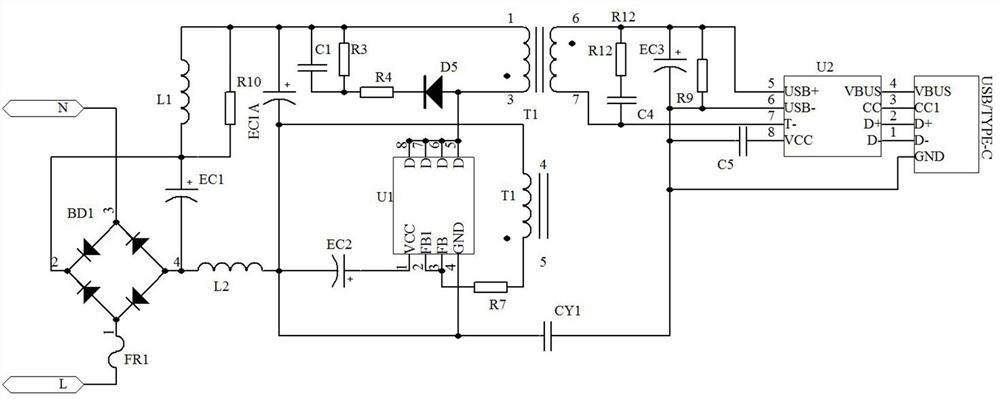
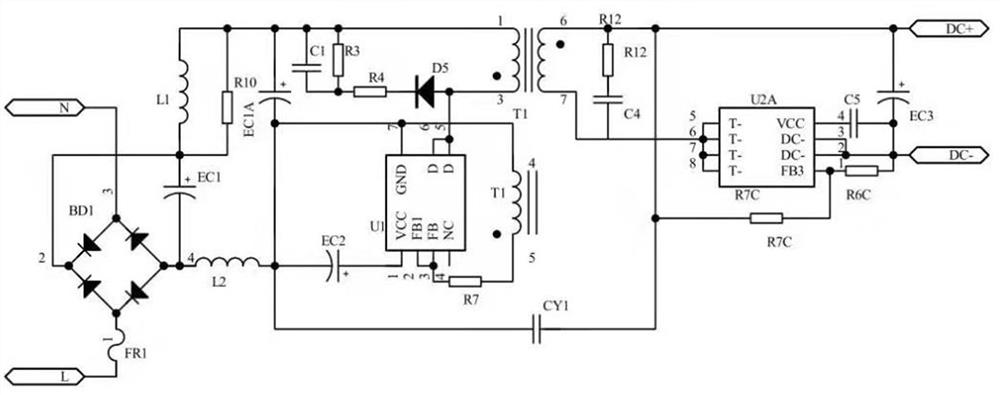
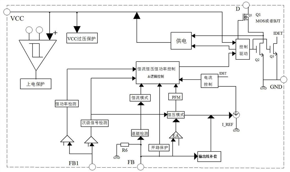
The invention belongs to the technical field of electronic loop detection and control and the field of switching power supplies, and relates to a bilateral feedback and control DSR architecture, which is different from conventional PSR and SSR architectures. It includes a primary circuit, the primary winding of which is connected to the main control chip U1, the main control chip U1 is connected to the auxiliary winding of the transformer T1, and the auxiliary winding is connected to the voltage dividing resistor to supply power to the FB1 pin of the main control chip U1, thereby The novel circuit detection and control circuit working mode is switched by the FB1 pin; the secondary circuit, as an output terminal, has a secondary main control chip U2 connected to its secondary winding, and a synchronous rectification module is built in the secondary main control chip U2; In CCM continuous and critical mode, it is necessary to avoid periodic feedback to prevent common failure. Usually, it is necessary to turn off or half turn off the synchronous drive in advance. At this time, the internal resistance of the synchronous mos tube increases, which causes the voltage of the secondary winding to rise, forming an envelope voltage. The network voltage mutual inductance is fed back to the primary FB1 pin, which is a new type of bilateral monitoring, feedback and processing circuit.

Description

technical field [0001] The invention belongs to the technical field of electronic loop detection and control and the field of switching power supplies, and relates to a bilateral feedback and control DSR architecture. Background technique [0002] As digital products such as mobile phones and computers have more and more functions, the power consumption required is increasing; coupled with the faster and faster pace of life, digital products such as mobile phones and computers need to be charged more quickly. To increase the speed, it is necessary to increase the current or change the voltage to improve the efficiency. In the past fast acting, the general structure is as follows: [0003] Usually, the SSR secondary side feedback architecture is required to feed back the output voltage and current, but the SSR architecture requires 431, optocoupler, voltage divider resistors and other devices to occupy space, and the conventional PSR cannot perform constant current and const...

Claims


Application Information

Patent Timeline
Patent Type & Authority Patents(China)
IPC IPC(8): H02M3/335
CPCH02M3/33592Y02B70/10
Inventor 严宗周
Owner SHENZHEN YUANNENG ELECTRIC CO LTD
Why Eureka
Try Eureka