Power supply conversion device

A technology of power conversion and voltage conversion circuit, which is applied in the direction of conversion equipment without intermediate conversion to AC, which can solve the problem of waste of circuit area and achieve the effect of suppressing the ringing phenomenon

Inactive Publication Date: 2009-12-23
NOVATEK MICROELECTRONICS CORP
View PDF0 Cites 7 Cited by
  • Summary
  • Abstract
  • Description
  • Claims
  • Application Information

AI Technical Summary

Problems solved by technology

However, in this method, in the process of chipping the circuit, an extra pin connected to terminal A must be added, resulting in a waste of circuit area.

Method used


Image

  • Power supply conversion device
  • Power supply conversion device
  • Power supply conversion device

Examples


no. 1 example

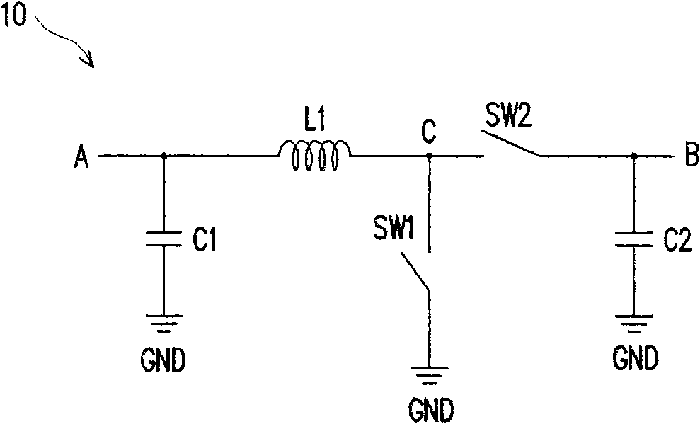
[0032] Please refer to the following Figure 2A , Figure 2A A schematic diagram of the power conversion device according to the first embodiment of the present invention is shown. The power conversion device 20 is a step-up power conversion device, including a switching voltage conversion circuit 210 and a potential adjustment circuit 220 . The switchable voltage conversion circuit 210 is composed of an inductor L1 , a voltage stabilizing capacitor C1 , a storage capacitor C2 , a switching switch SW1 , and a synchronous rectifier 211 . One end of the inductor L1 receives the input voltage VIN, the switching switch SW1 is connected in series between the other end of the inductor L1 and the ground voltage GND, one end of the synchronous rectifier 211, the other end of the inductor L1 and the switching switch SW1 are jointly coupled, and the synchronous rectifier 211 The other end produces the output voltage VOUT. The synchronous rectifier 211 is composed of a rectifier switc...

no. 2 example

[0045] Please refer to the following Figure 3A , Figure 3A A schematic diagram of a power conversion device according to a second embodiment of the present invention is shown. The power conversion device 30 is a step-down power conversion device, including a switching voltage conversion circuit 310 and a potential adjustment circuit 320 . The switchable voltage conversion circuit 310 is composed of an inductor L1 , a voltage stabilizing capacitor C2 , a storage capacitor C1 , a switching switch SW2 , and a synchronous rectifier 311 . One end of the switch SW2 receives the input voltage VIN, the other end of the switch SW2 is coupled to one end of the inductor L1, and the other end of the inductor L1 generates the output voltage VOUT. In addition, one end of the synchronous rectifier 311 is coupled to one end of the inductor L1 and the other end of the switch SW2 , and the other end of the synchronous rectifier 311 is coupled to the ground voltage GND. In addition, the syn...


PUM


Abstract

The invention discloses a power supply conversion device used for receiving input voltage, converting the input voltage and generating output voltage. The power supply conversion device comprises a switching type voltage conversion circuit and an electric potential regulation circuit, wherein the switching type voltage conversion circuit comprises an inductor, a switching switch and a synchronous rectifier, and the switching switch is used for switching off / switching on an energy storage action carried out in the inductor. The synchronous rectifier generates output voltage by way of electric energy stored in the energy storage action. Furthermore, the electric potential regulation circuit is bridged on the switching switch and used for lowering a voltage difference on both ends of the switching switch.

Description

technical field [0001] The present invention relates to a power conversion device, and in particular to a DC-to-DC power conversion device. Background technique [0002] With the advancement of electronic technology, people's requirements for electronic-related products are also increasing. In order to provide people with high-quality and low-cost commodities, how to effectively save the volume of electronic products has become an important topic for designers of electronic products today. Since in general electronic devices, multiple sets of power supplies are required to provide working voltages, in order to avoid using multiple bulky transformers to provide these different voltage power supplies, power converters have become the most popular among designers. A power supply device. [0003] However, a general DC-to-DC power conversion device (DC DC converter) uses a switch to complete its power conversion function, so a so-called ringing phenomenon inevitably occurs. Pl...

Claims


Application Information

Patent Timeline
Patent Type & Authority Applications(China)
IPC IPC(8): H02M3/10
Inventor 许庆勋
Owner NOVATEK MICROELECTRONICS CORP
Why Eureka
Try Eureka