Method and system for managing buffer areas

A management method and buffer technology, applied in transmission systems, store-and-forward switching systems, electrical components, etc., can solve problems such as low performance, out-of-order, performance impact, etc., to improve performance, improve response speed, and save space consumption. Effect

Inactive Publication Date: 2009-12-23
ZTE CORP
View PDF0 Cites 11 Cited by
  • Summary
  • Abstract
  • Description
  • Claims
  • Application Information

AI Technical Summary

Problems solved by technology

In addition, this 2Bit access cannot be accessed together with the free buffer queue, because the content in the free buffer queue is out of order
Therefore, if the automatic recovery system is adopted, when the buffer is recovered, the read and write accesses to the external memory will be added once each, which will seriously affect the performance
[0007] Considering the buffer recycling function, the traditional buffer management system manages the buffer quantity of 1M, and the required space is at least: 1M*20+1M*2=22Mbit, which requires huge space and low performance

Method used


Image

  • Method and system for managing buffer areas
  • Method and system for managing buffer areas
  • Method and system for managing buffer areas

Examples


Embodiment Construction

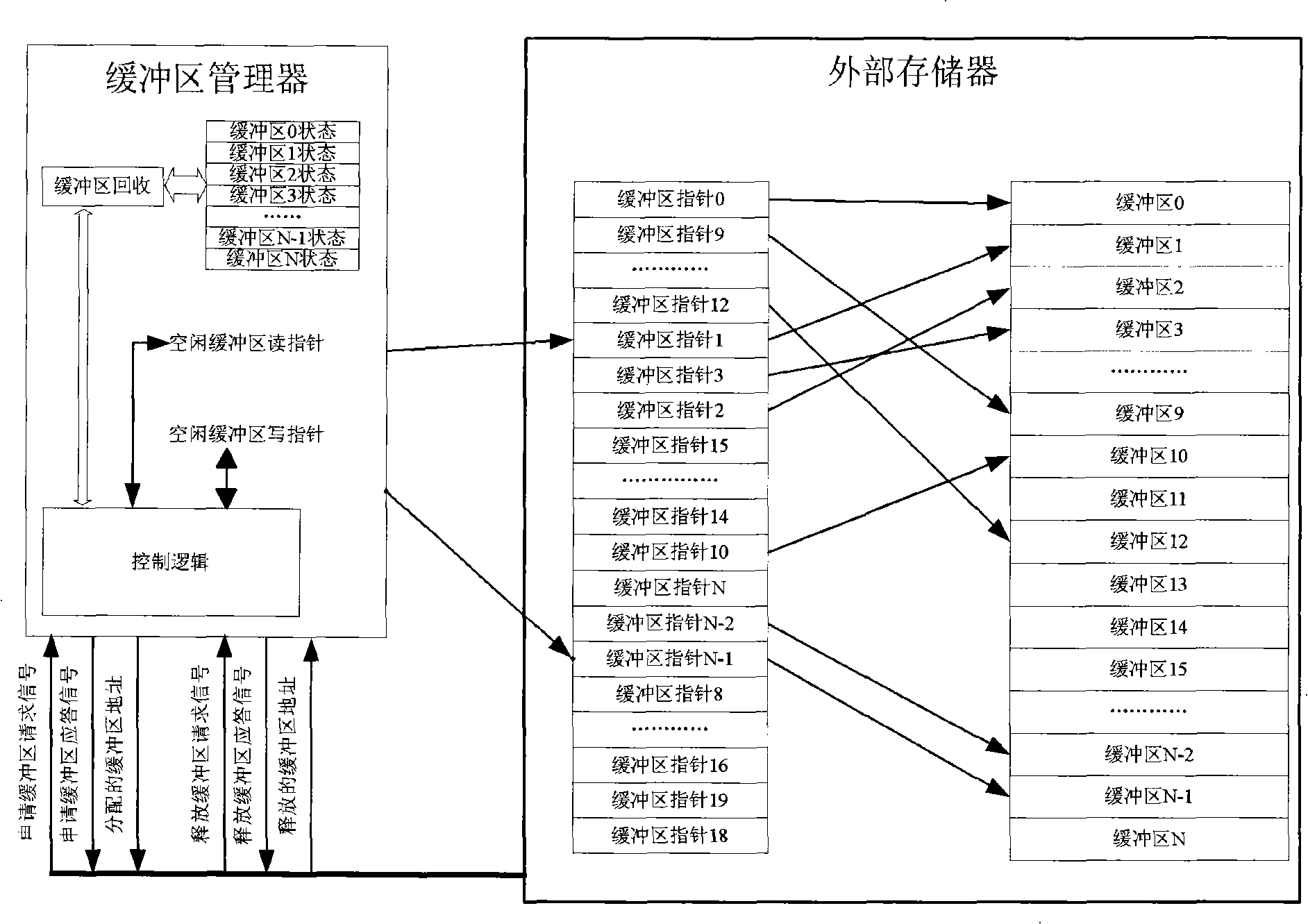
[0032] First, explain the composition, key and features of the present invention:

[0033] The present invention maintains a buffer status table with a bit width of 1 bit and a length equal to the number of buffers. The index of the buffer status table corresponds to each buffer, and the index width is consistent with the address width of the buffer. The content of the buffer status table identifies whether the corresponding buffer is allocated. For example, 1 means unallocated status, and 0 means Assigned status. In order to speed up the response speed, the present invention divides the buffer status table into several sub-tables for maintenance. Each buffer status sub-table has a sub-table ID. The sub-table ID numbers start from 0 and are numbered 1, 2, 3.. ... The buffer status sub-table ID as the high bit and the index of the buffer status sub-table as the low bit constitute the buffer address. In addition, in order to realize the buffer recovery function, the present inventio...


PUM


Abstract

The invention relates to a method and a system for managing buffer areas. The system is wholly built in a chip connected with an external storage, and the method comprises the following steps: establishing a buffer area state table of the external storage and ensuring that the record index of the table is the same as an address of respective buffer area; and distributing or recovering the buffer areas according to corresponding requests and the buffer area state table, and maintaining the buffer area state table. The method and the system use the state table of storage buffer areas to replace a pointer of the storage buffer areas through the direct correspondence of the record index and the addresses of the buffer areas, so that the entire system can be achieved completely in the chip, and compared with the prior method for managing the buffer areas, the method greatly saves the space consumption of the storage, greatly improves the performance representation, further divides the entire buffer area state table into a plurality of subtables, and greatly improves the response speed which is much faster than that of the prior method.

Description

Technical field [0001] The invention relates to high-speed data transmission and exchange, in particular to a buffer management method and system. Background technique [0002] In the data communication network, the data traffic is very large. These data flows complete the intercommunication between the source port and the destination port at a data exchange point, which includes a switch, a router, and the like. At each data exchange point, generally due to data processing needs, data messages coming in from the source port need to be buffered. [0003] In the field of data communication, large-capacity memory is usually used to store data coming in from the source port. Large-capacity memory is usually synchronous dynamic random access memory (SDRAM), double data transmission synchronous dynamic random access memory (DDR SDRAM), quadruple data transmission synchronous dynamic random access memory (DDR2SDRAM), etc. The memory is divided into many small blocks as needed, and thes...

Claims


Application Information

Patent Timeline
Patent Type & Authority Applications(China)
IPC IPC(8): H04L12/54H04L29/08H04L49/901
Inventor 吴春华娄本刚
Owner ZTE CORP
Why Eureka
Try Eureka