Method and device for encapsulating electronic components using underpressure

A technology for electronic components and vacuum packaging, which is applied in electrical components, electric solid-state devices, semiconductor devices, etc., and can solve problems such as the quality of packaging not reaching the expected effect.

Active Publication Date: 2009-12-23
BESI NETHERLANDS BV
View PDF0 Cites 9 Cited by
  • Summary
  • Abstract
  • Description
  • Claims
  • Application Information

AI Technical Summary

Problems solved by technology

This method has been used in practice, but the package quality is no...

Method used


Image

  • Method and device for encapsulating electronic components using underpressure
  • Method and device for encapsulating electronic components using underpressure
  • Method and device for encapsulating electronic components using underpressure

Examples


Embodiment Construction

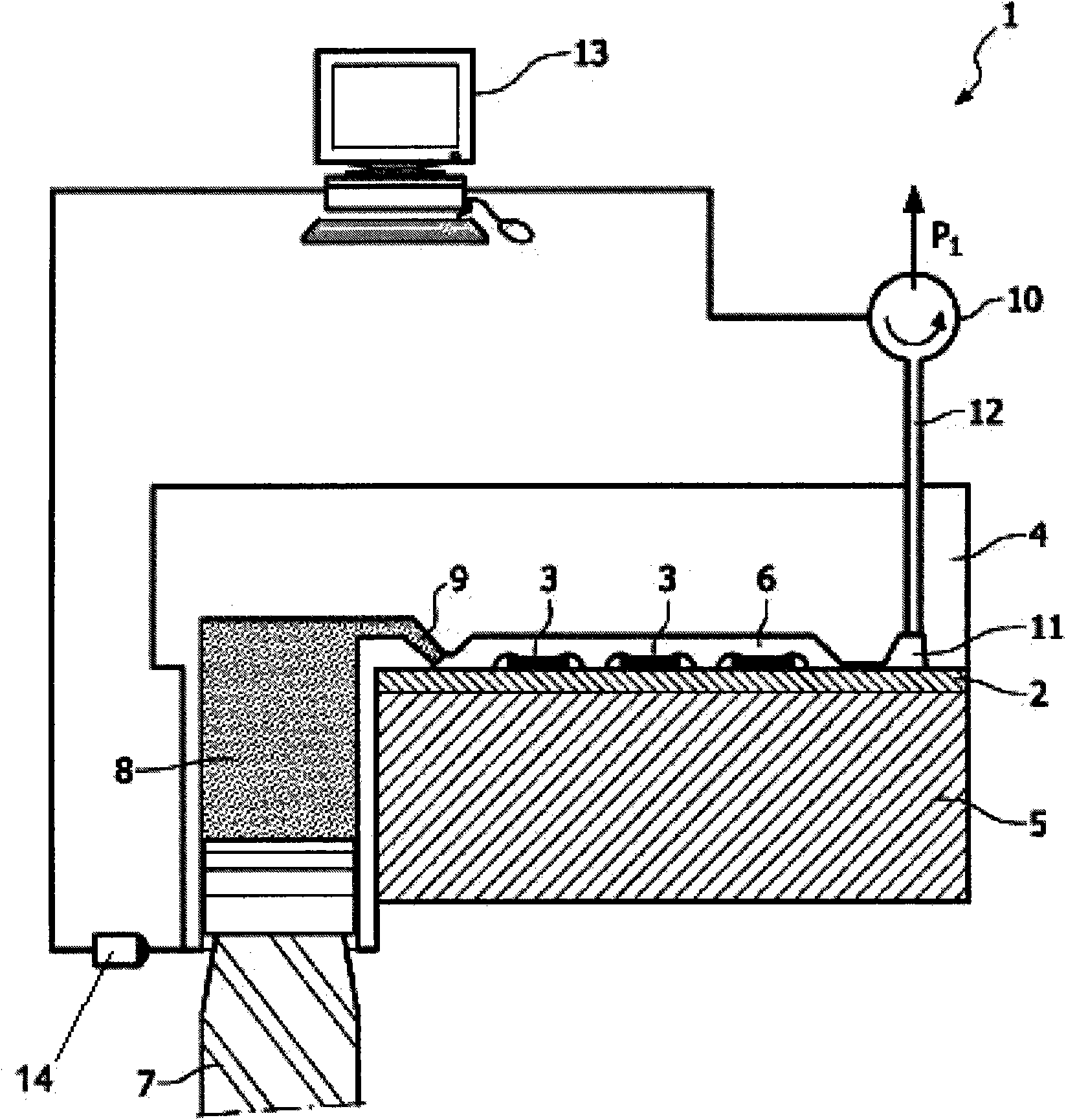
[0022]FIG. 1 shows a device 1 for packaging electronic components 3 arranged on a carrier 2 . The carrier is clamped between the two mold parts 4 , 5 , so that the electronic component 3 can be accommodated here in the mold cavity 6 , which is to the left of the upper mold part 4 . The encapsulating material 8 becomes liquid after being heated, and enters the mold cavity 6 through the gate 9 under the push of the piston 7 . In order to make the packaging material 8 fill the mold cavity better, gas (usually air, and possibly the gas volatilized in the packaging material) can be pumped out to the external environment through the pumping chamber 11 and the pumping channel 12 under the action of the pump 10 in (see arrow P 1 ).

[0023] The device 1 further includes an intelligent controller 13, which is shown as a computer in this figure. Preferably, the computer is equipped with multiple menu programs for use. The vacuuming process in the mold cavity 6 is controlled. The sma...


PUM


Abstract

The invention relates to a method for encapsulating electronic components mounted on a carrier using underpressure, comprising the processing steps of: A) placing an electronic component in a mould cavity, B) heating encapsulating material, C) displacing the encapsulating material to the mould cavity, D) filling the mould cavity, and E) curing the encapsulating material in the mould cavity. The invention also relates to a device with which such a method can be performed.

Description

technical field [0001] The invention relates to a method for vacuum packaging an electronic component arranged on a carrier, comprising the steps of: A) placing the electronic component to be packaged in a mold cavity connected to the carrier, B) heating the packaging material to make it liquid, C ) filling the cavity containing the electronic component by applying pressure to the liquid encapsulating material, D) filling the cavity with the encapsulating material, E) curing the filling material in at least a portion of the cavity; wherein, at least in step B )-D) Dynamically control the vacuuming process in the mold cavity. [0002] The present invention also relates to a device for packaging electronic components arranged on a carrier by vacuum pumping, comprising: a mold part, each component part of which is detachably connected to each other, and in a closed state at least defines a cavity for placing electronic components. Mold cavity; filling means for connecting liquid...

Claims


Application Information

Patent Timeline
IPC IPC(8): H01L21/56B29C45/34B29C45/76
CPCH01L24/97B29C45/02B29C45/34B29C2945/76381H01L23/3121H01L21/56B29C2945/76859B29C2945/762B29C45/76B29C2945/76083B29C2945/76498B29C45/14655H01L2224/48091B29C2945/76735H01L21/565H01L2924/00014
Inventor J·L·G·M·范如志W·G·J·加尔L·F·W·范·哈恩
Owner BESI NETHERLANDS BV
Why Eureka
Try Eureka