Hydrocarbon retaining system configuration for an internal combustion engine

A hydrocarbon and retention system technology, applied in the direction of internal combustion piston engines, combustion engines, engine components, etc., can solve problems such as prolonged extraction operation, increased cold start emissions, etc.

Inactive Publication Date: 2009-12-30
FORD GLOBAL TECH LLC
View PDF0 Cites 6 Cited by
  • Summary
  • Abstract
  • Description
  • Claims
  • Application Information

AI Technical Summary

Problems solved by technology

Also, if the engine is stopped before the stored hydrocarbons are sufficiently purged, emissions from subsequent cold starts may increase
Also, extended pumping runs may limit other runs, such as adaptive fuel learning, etc.

Method used


Image

  • Hydrocarbon retaining system configuration for an internal combustion engine
  • Hydrocarbon retaining system configuration for an internal combustion engine
  • Hydrocarbon retaining system configuration for an internal combustion engine

Examples


Embodiment Construction

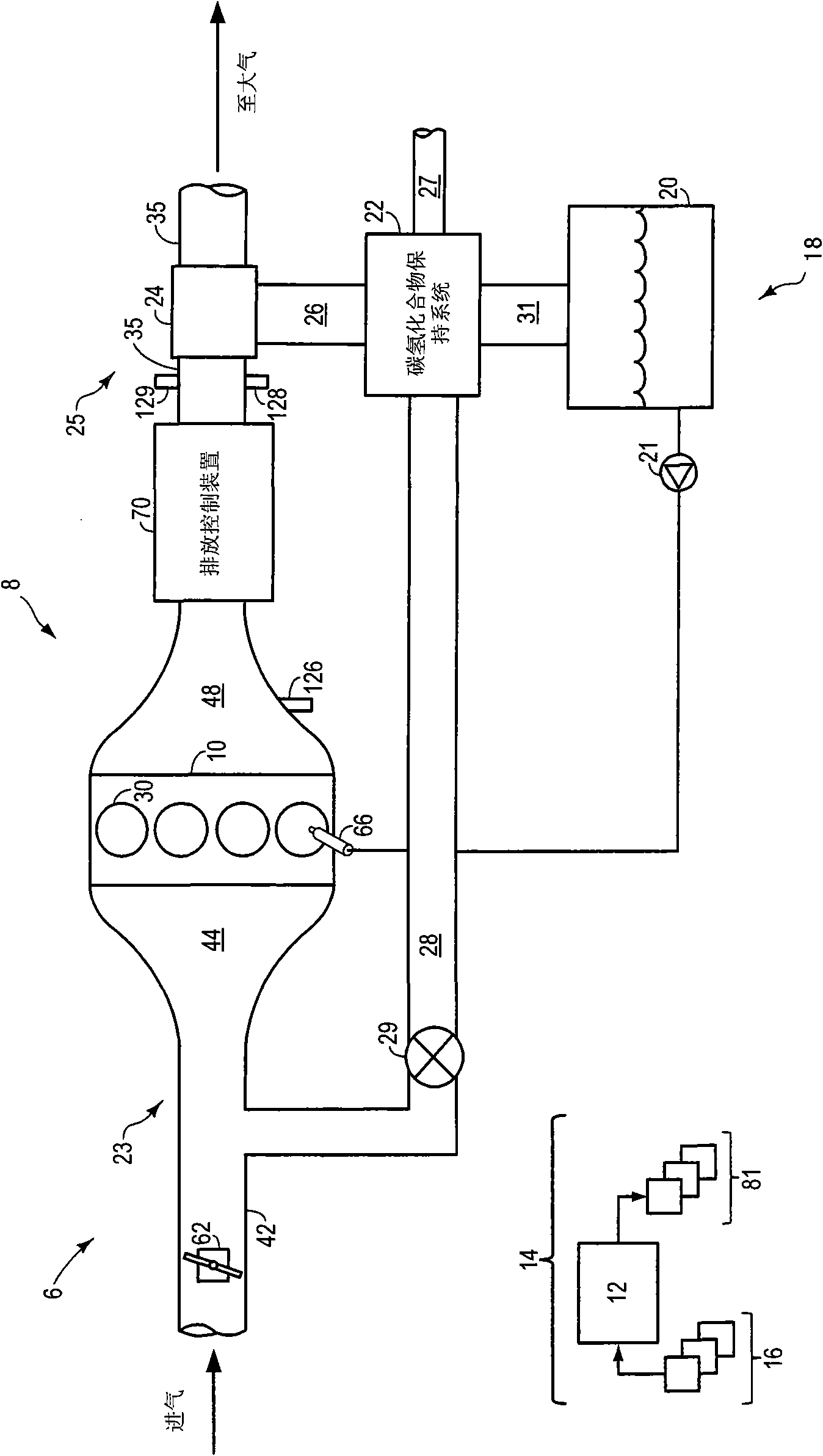
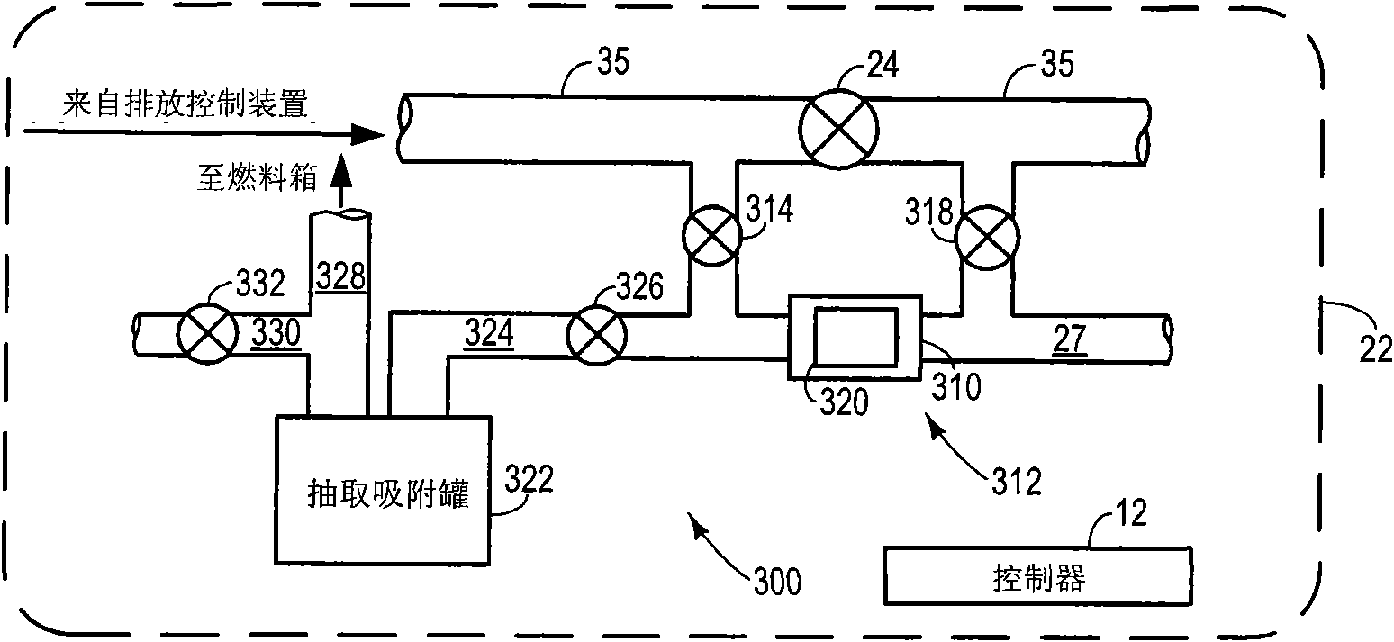
[0012] figure 1 A schematic diagram of a vehicle system 6 is shown. Vehicle system 6 includes engine system 8 connected to hydrocarbon (HC) retention system 22 and fuel system 18 .

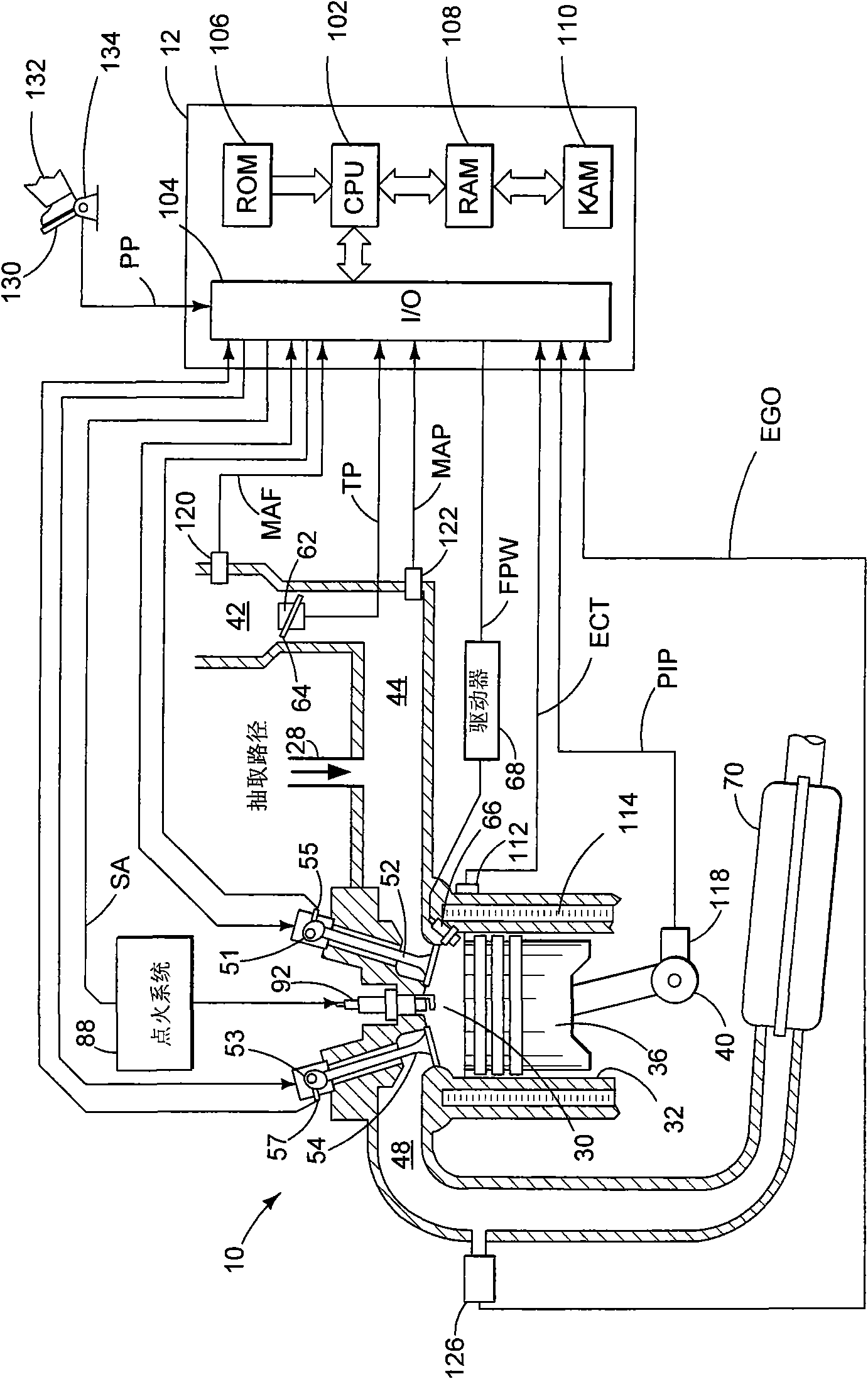
[0013] Engine system 8 may include engine 10 having a plurality of cylinders 30 . Engine 10 includes an intake system 23 and an exhaust system 25 . Intake system 23 includes throttle 62 fluidly coupled to engine intake manifold 44 via intake passage 42 . Exhaust system 25 includes an exhaust manifold 48 that leads to exhaust passage 35 that delivers exhaust to atmosphere. Exhaust system 25 may include one or more emission control devices 70 that may be mounted in close-coupled locations within the exhaust system. The one or more emission control devices may include a three way catalyst, a lean NOx trap, a diesel particulate filter, an oxidation catalyst, and the like. should be clearly as figure 2 As shown in the example engine of , other components such as various valves and sensors may be...


PUM


Abstract

The invention relates to a hydrocarbon retaining system configuration for an internal combustion engine, describing a system and a method for managing exhaust of a vehicle engine, wherein during start-up of the engine, exhaust gas is transferred to a hydrocarbon retaining device and is extracted to an intake manifold of the engine. The invention describes a plurality of replaceable methods for controlling operation and diagnosing deterioration. In addition, the invention also describes a plurality of associated configurations. The invention can improve the extraction of hydrocarbon remained in an air intake system of the engine by using heat of exhaust gas.

Description

【Technical field】 [0001] The present invention generally relates to an exhaust gas treatment system for an internal combustion engine. 【Background technique】 [0002] Engine exhaust systems have utilized hydrocarbon retention devices, such as hydrocarbon traps, to retain cold start emissions for late reactions or to recirculate into the engine intake system. In one specific example, extraction of exhaust gas may begin when the device reaches a predetermined temperature. [0003] However, the inventors have recognized some problems with this example. For example, desorption of stored hydrocarbons may occur over a considerable duration in some cases. Also, if the engine is stopped before the stored hydrocarbons are sufficiently purged, emissions from subsequent cold starts may increase. Additionally, extended purging operations may limit other operations, such as adaptive fuel learning and the like. 【Content of invention】 [0004] In one approach, the above problems may ...

Claims


Application Information

Patent Timeline
IPC IPC(8): F02M25/00
CPCB01D2253/102B01D53/9481Y02T10/47F01N9/00B01D2253/108Y02T10/40
Inventor 迈克尔·詹姆士·乌里奇夏恩·埃尔沃特詹姆士·迈克尔·克恩兹詹森·亚伦·卢佩斯库
Owner FORD GLOBAL TECH LLC
Why Eureka
Try Eureka