Microchannel condenser

A condenser and micro-channel technology, which is applied in the field of parallel-flow condensers for micro-channels, can solve problems such as unreasonable flow path design, and achieve the effects of reasonable structural design, enhanced pressure resistance, and improved heat exchange efficiency

Inactive Publication Date: 2009-12-30
ZHEJIANG KANGSHENG CO LTD
View PDF3 Cites 26 Cited by
  • Summary
  • Abstract
  • Description
  • Claims
  • Application Information

AI Technical Summary

Problems solved by technology

[0007] The purpose of the present invention is to solve the unreasonable problems of existing condenser fins and heat exchange tube structures, the distance between fins and heat exchange tubes, the thickness of heat exchange...

Method used


Image

  • Microchannel condenser
  • Microchannel condenser
  • Microchannel condenser

Examples


Embodiment 1

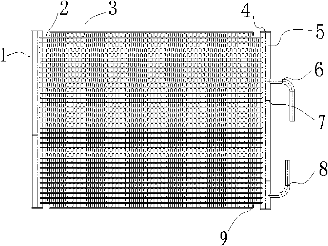
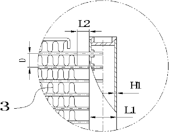
[0024] Embodiment one, see figure 1 and figure 2 , this micro-channel condenser includes two parallel left headers 1 and right headers 5, between the two headers is provided with multi-layer flat tubes 2, the flat tubes 2 communicate with the inner chambers of the two headers, in the flat There are fins 3 extending in a sine wave between the tubes 2, and a partition 7 is inserted in the inner cavity of the two headers. The partition 7 seals and separates the two headers into multiple chambers, namely, the inlet tube and the inlet tube. Working area of ​​the outlet pipe.

[0025] End caps 4 capable of sealing the headers are respectively provided at both ends of the left and right headers, and an inlet pipe 6 and an outlet pipe 8 are arranged on the right header 5 .

[0026] The upper and lower sides of the flat tube 2 are respectively provided with side plates 9 , and fins 3 are also provided between the flat tube 2 and the side plates 9 .

[0027] Both the header and the ...

Embodiment 2

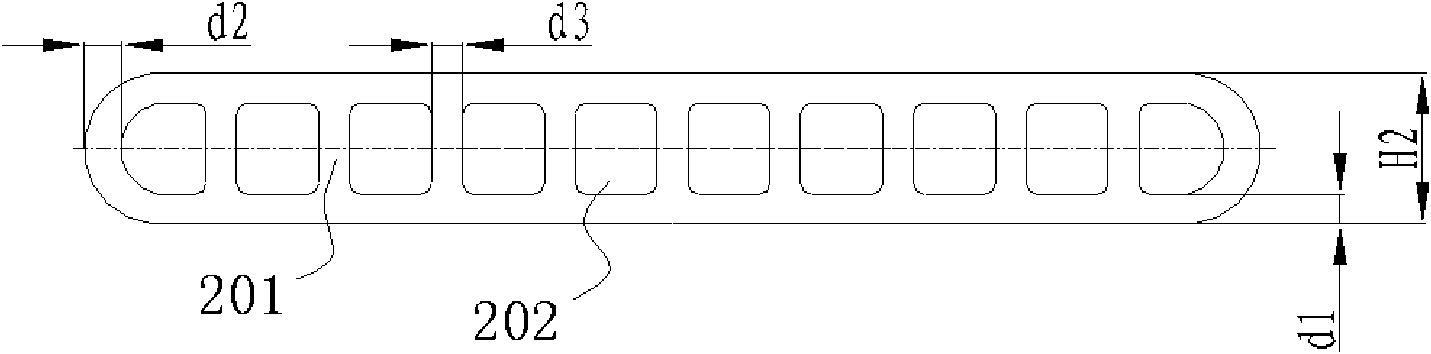
[0031] Embodiment 2, the structure of this embodiment is similar to that of Embodiment 1, the difference is that the outer diameter and wall thickness of the header are 26 ± 1 mm × 1.9 ± 0.2 mm, the width of the flat tube is set to 20 ± 0.2 mm, and the number of holes inside the flat tube The number is 12, and the width of the fins 3 is also set to 20±0.2mm.

Embodiment 3

[0032] Embodiment 3, the structure of this embodiment is similar to that of Embodiment 1, the difference is that the outer diameter and wall thickness of the header are 32 ± 1 mm × 2.5 ± 0.2 mm, the width of the flat tube is set to 25 ± 0.2 mm, and the number of holes inside the flat tube The number is 14, and the width of the fins 3 is also set to 25±0.2mm.

[0033] Similarly, the header, the flat tube 2, the number of holes in the flat tube and the fins 3 have other optimal size configurations.


PUM

PropertyMeasurementUnit
Wall thicknessaaaaaaaaaa
Side wall thicknessaaaaaaaaaa
Heightaaaaaaaaaa

Abstract

The invention relates to a microchannel parallel-flow condenser, in particular to a high-working-pressure high-heat-exchange-rate parallel-flow condenser using CO2, R410a, 407C, R22 and other cold media. The condenser comprises two parallelly placed collectors which are a left collector and a right collector, a plurality of flat tubes which are arranged between the two collectors and are communicated with the inner cavities of the collectors, partition boards which are inserted into the collectors and airtightly divide the collectors into a plurality of chambers, end closures which are arranged at two ends of the collectors to seal the collectors, inlet and outlet pipes which are arranged on the collectors and side plates arranged on up and down two sides of the flat tubes. The condenser is characterized in that: fins extending and distributing in a sine wave are arranged between the flat tubes; the fins are arranged between the flat tubes and the side plates; the tube spacing is 9 to 11 millimeters; and the thickness of the flat tubes is 1.8 to 2.22 millimeters.

Description

technical field [0001] The invention relates to a parallel flow condenser for microchannels, in particular to the use of CO 2 , R410a, 407C, R22 and other refrigerants with high working pressure and high heat exchange efficiency parallel flow microchannel condenser. Background technique [0002] Microchannel heat exchangers, also known as parallel flow heat exchangers, are heat exchangers in which refrigerants and refrigerants flow along channels with a diameter less than a few millimeters. This type of heat exchanger is currently widely used in automotive air conditioners. [0003] As people's awareness of energy saving increases, the requirements for high-efficiency heat exchange performance of heat exchangers are getting higher and higher. There are many factors that affect the heat exchange performance of heat exchangers, including fin structure, heat exchange tube structure, fin and heat exchange tube Factors such as the spacing of the heat exchange material, the thick...

Claims


Application Information

Patent Timeline
IPC IPC(8): F28D1/053F28F1/30F28F1/02F28F9/02F28F3/04F25B39/04
CPCF28F1/126F28F2260/02F28D1/05391F28D2021/007
Inventor 陈汉康成守权闫志恒许显钧
Owner ZHEJIANG KANGSHENG CO LTD
Why Eureka
Try Eureka