
Multi-fuel internal combustion engine

A technology for internal combustion engines and fuels, applied to internal combustion piston engines, adding non-fuel substances to fuel, combustion engines, etc., can solve the problems of deterioration of emission performance and drivability, limited reduction of injection volume, and inability to suppress emission performance, etc., to achieve suppression Deterioration of exhaust emission performance and drivability, effect of good running

Inactive Publication Date: 2009-12-30
TOYOTA JIDOSHA KK
View PDF4 Cites 6 Cited by
  • Summary
  • Abstract
  • Description
  • Claims
  • Application Information

AI Technical Summary

Problems solved by technology

For this reason, even if the purification control is performed according to the concentration of alcohol in the fuel tank as in the above-mentioned Patent Documents 3 and 4, the actual air-fuel ratio in the combustion chamber may become too high due to the inflow of a single low-boiling point component. It is rich in the target air-fuel ratio, so in this case, it may lead to deterioration of emission performance and drivability
[0010] Here, although the following point of view can also be established, that is, the injection amount of the fuel injection valve can be suppressed by considering the inflow amount of a single low boiling point component into the combustion chamber. However, there is a limit to the reduction of the injection amount. Even if the injection amount is reduced to the minimum injection amount of the fuel injection valve, if a single low-boiling point component that is larger than the reduced amount flows into the combustion chamber, the actual amount in the combustion chamber It is conceivable that the air-fuel ratio becomes too rich than the target air-fuel ratio (rich), and the deterioration of emission performance cannot be suppressed.

Method used


Image

  • Multi-fuel internal combustion engine
  • Multi-fuel internal combustion engine
  • Multi-fuel internal combustion engine

Examples


Embodiment 1

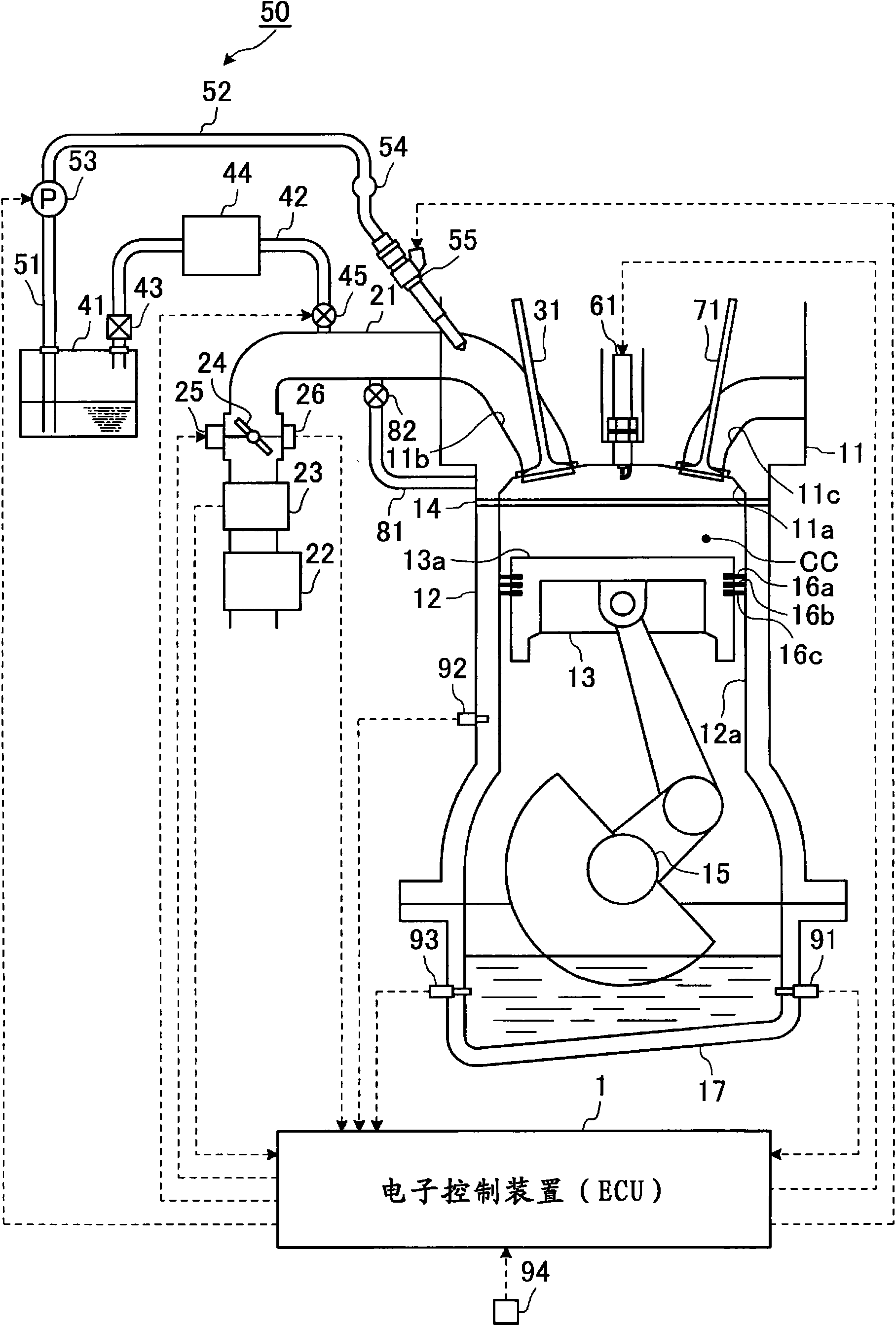
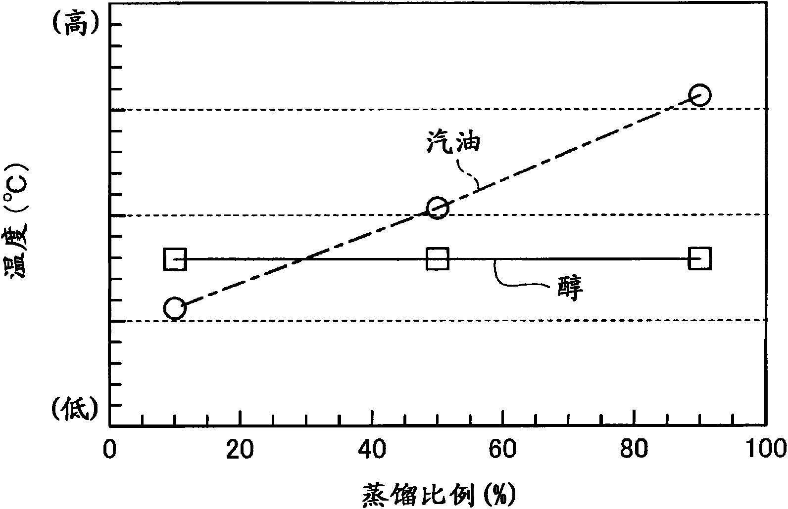
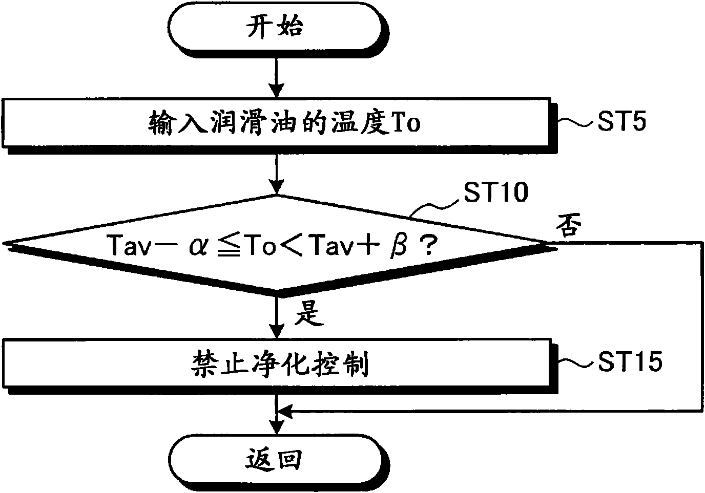
[0027] based on Figure 1 to Figure 3 Embodiment 1 of the multi-fuel internal combustion engine according to the present invention will be described. The multi-fuel internal combustion engine of Embodiment 1 refers to storing a single low-boiling point component fuel and at least one fuel mixture whose property state is different from the single low-boiling point component fuel in one fuel tank, and using the mixed fuel to operate internal combustion engine, through figure 1 The electronic control unit (ECU) 1 shown performs various control operations such as combustion control. The electronic control device 1 is composed of a CPU (Central Processing Unit) not shown, a ROM (Read Only Memory) in which predetermined control programs and the like are stored in advance, a RAM (Random Access Memory) in which temporarily stores calculation results of the CPU, and Consists of backup RAM, etc. to store pre-prepared information, etc. In addition, the single low-boiling-point compone...

Embodiment 2

[0061] Below, based on figure 1 and Figure 4 Embodiment 2 of the multi-fuel internal combustion engine related to the present invention will be described.

[0062] In the multi-fuel internal combustion engine of the above-mentioned embodiment 1, if the temperature To of the lubricating oil in the oil pan 17 has entered the specified purification control prohibition temperature range (Tav-α≤To

[0063] However, the lubricating oil in the oil pan 17 is not always mixed with the same amount of alcohol fuel (single low-boiling point component fuel), and it is not ideal to completely prohibit purge control using only the temperature To of the lubricating oil. That is to say, when the amount of alcohol fuel mixed in the lubricating oil is small, the amount of alcohol fuel evaporated from the lubricating oil is also small, so when operating conditions that require a large amount of purge ...

Embodiment 3

[0080] Below, based on figure 1 , Figure 5 and Figure 6 Embodiment 3 of the multi-fuel internal combustion engine according to the present invention will be described.

[0081] The multi-fuel internal combustion engine of the present embodiment 3 is a modified example of the multi-fuel internal combustion engine of the above-mentioned embodiment 2, and the mixing amount of the single low-boiling point component fuel (alcohol fuel) into the lubricating oil in the oil pan 17 is also considered. Based on which to judge whether to prohibit the decontamination control.

[0082] Specifically, in the third embodiment, the configuration is as follows: instead of comparing the detected or estimated dilution rate Ro of lubricating oil with the predetermined value (predetermined dilution rate) Ra as in the second embodiment, The lubricating oil dilution ratio Ro is controlled by a purge control prohibition temperature range (Tav-α≤To<Tav+β) that is a threshold for judging whether pu...


PUM


Abstract

This invention provides a multi-fuel internal combustion engine. The multi-fuel internal combustion engine is operated by leading a single low-boiling point component fuel and at least one fuel different from the single low-boiling point component fuel in properties either each solely or together to a combustion chamber (CC). The multi-fuel internal combustion engine comprises lubricating oil temperature detecting means (temperature sensor (91)) for detecting the temperature of a lubricating oil or lubricating oil temperature estimating means for estimating the temperature of the lubricating oil, and purge control means (electronic control unit (1)) which, when the temperature of the detected or estimated lubricating oil is around the boiling temperature of the single low-boiling point component fuel, prohibits purge control by an evaporation gas purge apparatus (comprising an evaporation gas passage (42), a check valve (43), a canister (44), and an opening / closing valve (45)), or reduces the purge flow rate of the evaporation gas in the purge control.

Description

technical field [0001] The present invention relates to a multi-fuel internal combustion engine that operates using a single low-boiling component fuel typified by alcohol fuel and at least one fuel whose property state is different from the single low-boiling component fuel. Background technique [0002] Generally, fuel evaporation gas is generated by evaporation of fuel stored in the fuel tank. The fuel tank is generally sealed, and its internal pressure rises with the increase of the boil-off gas, so if the pressure is not released to the outside, damage or the like may occur. However, since this boil-off gas contains harmful hydrocarbon (HC) components, for example, if it is a product of gasoline fuel evaporated, it cannot be directly discharged into the atmosphere from the viewpoint of environmental performance. Therefore, in the past, in the internal combustion engine, the evaporated gas is prepared to be adsorbed by the activated carbon in the canister, and introduce...

Claims


Application Information

Patent Timeline
Patent Type & Authority Applications(China)
IPC IPC(8): F02M25/08F02D19/06F02D19/08F02D45/00
CPCF02M25/089F02D41/0025F02D41/047Y02T10/36F02D2250/11F02M25/06F02D41/0032F02D19/084F02D2200/023Y02T10/30
Inventor 角冈卓渡边刚细川阳平
Owner TOYOTA JIDOSHA KK
Learn More