Electric fan for sewing machine

A technology of electric fan and sewing machine, applied in sewing machine components, sewing equipment, mechanical equipment, etc., can solve the problems of resource waste, high cost, stuffy workshop, etc., and achieve the effects of improving work efficiency, simple structure, and convenient installation

Inactive Publication Date: 2010-01-06
叶信平
View PDF1 Cites 4 Cited by
  • Summary
  • Abstract
  • Description
  • Claims
  • Application Information

AI Technical Summary

Problems solved by technology

[0002] At present, garment factories generally use small ceiling fans suspended in the air to cool down the operators. The ceiling fans are bulky, occupy a lot of space, and are not beautiful. Moreover, the wind blows towards the surroundings, and only part of the wind blows towards the operators, which causes a waste of resources. The power of the small ceiling fan is relatively large (more than 10 watts), and the power consumption
Although a small fan for sewing machines that has been applied for (patent application number 200910142472.X) solves the above problems, it needs a voltage transformer, which has a complicated structure and high cost
Some garment factories also use air conditioners to cool down the workshop, usually at the highest temperature, and do not use the air conditioner when the temperature is lower, the workshop is still hot

Method used


Image

  • Electric fan for sewing machine
  • Electric fan for sewing machine
  • Electric fan for sewing machine

Examples


Embodiment 1

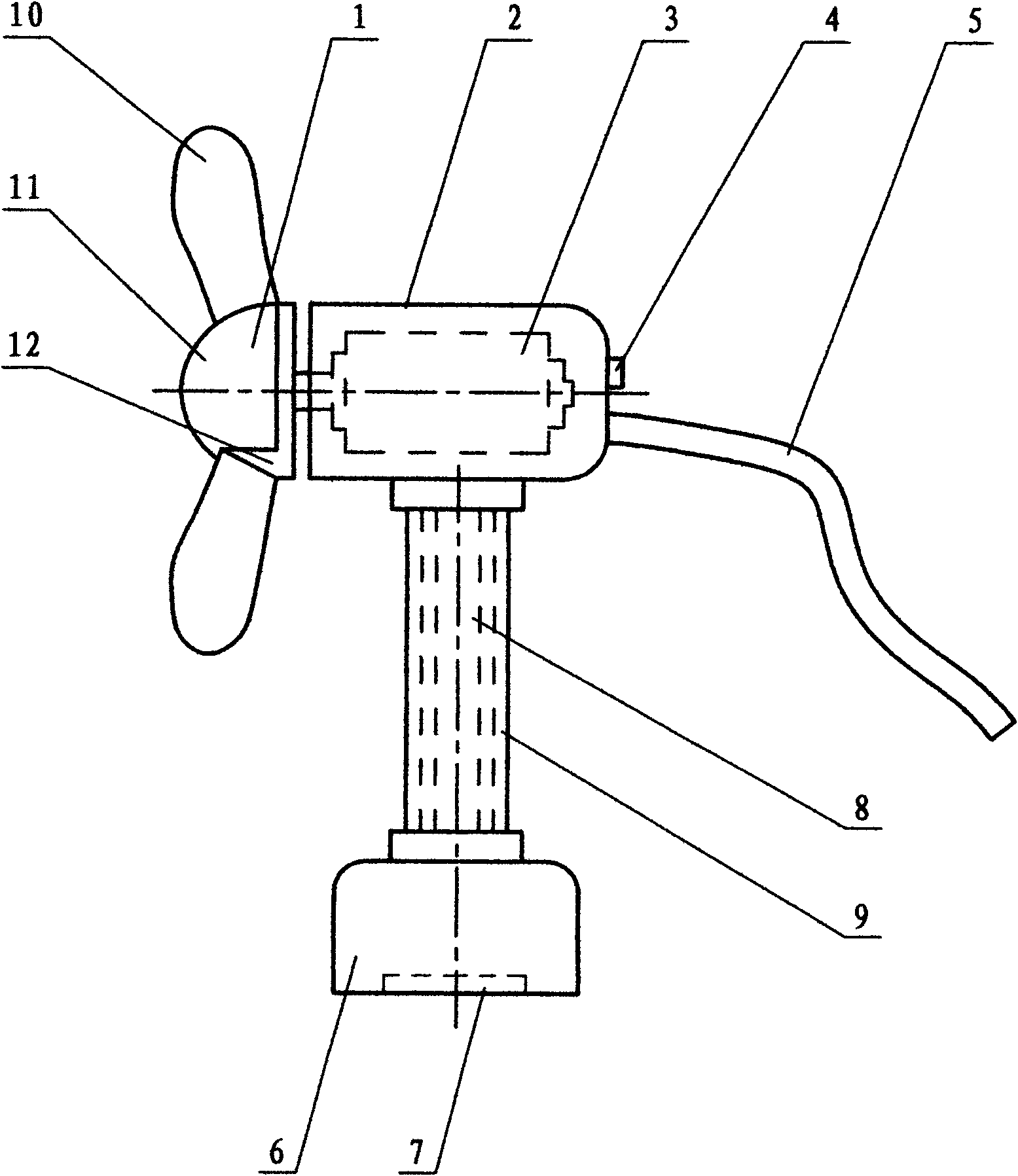
[0024] Embodiment 1: as figure 1 , an electric fan for sewing machines, comprising a fan head 1, a casing 2, a motor 3, a switch 4, a power cord 5, a base 6, and a pole 8, the motor 3 is arranged in the casing 2, and the fan head 1 is arranged on the extension of the motor 3 At the end of the output shaft, the bottom surface of the base 6 is provided with a magnet 7, and the pole 8 is connected to the shell 2 and the base 6. One end of the power cord 5 is connected to the motor 3, and the other end is directly connected to the external power supply (motor switch). The device has a simple structure. The bottom surface of base 6 is provided with magnet 7, and electric fan can be directly adsorbed on the sewing machine body, and pole 8 is a metal hose, which can be bent in any direction, so that fan head 1 is blown toward the operator, and is easy to install. A bellows 9 is established outside the pole 8, which is decorative and attractive. Switch 4 controls the motor to rotate...

Embodiment 2

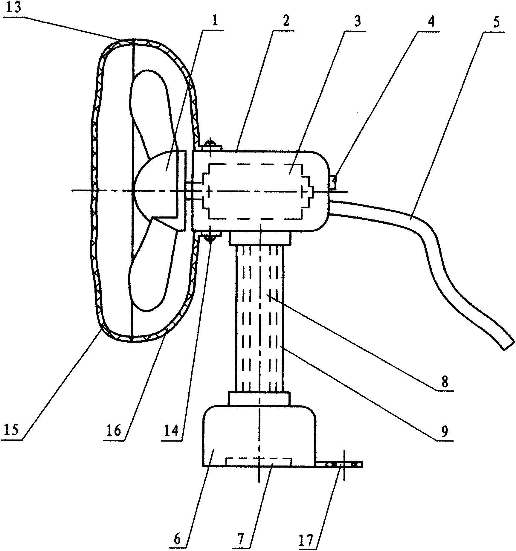
[0025] Embodiment 2: as figure 2 , an electric fan for sewing machines, when the fan head 1 is molded with integral plastic, a fan cover 13 is added on the outside so that the operator cannot touch the fan head 1, which is safer. The fan cover 13 is made up of a front cover 15 and a rear cover 16, and is locked on the casing 2 with screws 14. Fan cover 13 is net shape, and many ventilation grooves are arranged above. The bottom surface of the base 6 is provided with a mounting hole 17. When the magnet is not installed, the base 6 can be locked on the sewing machine with screws, which saves costs. Other structures are the same as in Embodiment 1, and will not be described in detail again.

Embodiment 3

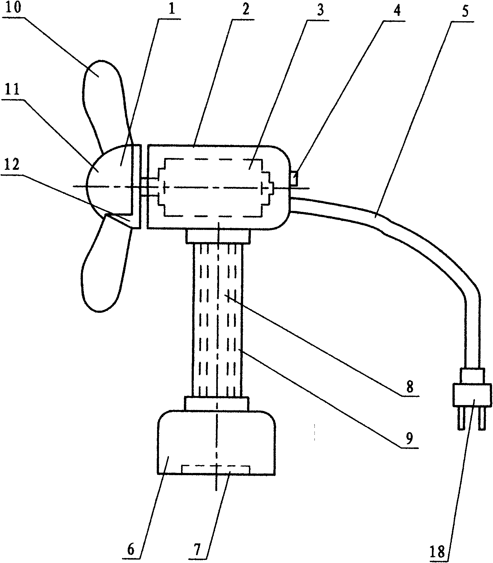
[0026] Embodiment 3: as image 3 , an electric fan for sewing machines, one end of a power cord 5 connected to an external power supply is provided with a two-pin two-pin plug 18, which can also be a three-pin plug, which is more convenient to install. Other structures are the same as in Embodiment 1, and will not be described in detail again.


PUM


Abstract

The invention relates to an electric fan for a sewing machine, comprising a fan head 1, an outer shell 2, a motor 3, a switch 4, a power line 5, a base 6 and a supporting rod 8, wherein the motor 3 is arranged in the outer shell 2, the fan head 1 is arranged at the tail end of an extending shaft of the motor 3, the bottom surface of the base 6 is provided with a magnet 7, the supporting rod 8 is connected with the outer shell 2 and the base 6, and one end of the power line 5 is connected with the motor 3. The electric fan for a sewing machine is characterized in that the other end of the power line 5 is directly connected with an external power supply. The electric fan for a sewing machine has simple structure and low cost, is convenient to install, saves energy and is beautiful and safe.

Description

technical field [0001] The invention relates to an electric fan, in particular to an electric fan for a sewing machine. Background technique [0002] At present, garment factories generally use small ceiling fans suspended in the air to cool down the operators. The ceiling fans are bulky, occupy a lot of space, and are not beautiful. Moreover, the wind blows towards the surroundings, and only part of the wind blows towards the operators, which causes a waste of resources. Small ceiling fans have relatively high power (more than 10 watts) and consume electricity. Although a small fan for sewing machines that has been applied for (patent application number 200910142472.X) solves the above-mentioned problems, it needs a voltage changing device, which has a complicated structure and high cost. Some garment factories also use air conditioners to cool down the workshop, usually at the highest temperature, and do not use air conditioners when the temperature is slightly lower, so ...

Claims


Application Information

Patent Timeline
Patent Type & Authority Applications(China)
IPC IPC(8): F04D25/08D05B81/00
Inventor 叶信平
Owner 叶信平
Why Eureka
Try Eureka