Method for remanufacturing photosensitive drum into another photosensitive drum

One kind of photosensitive drum and another kind of technology are applied in the fields of optics, solid waste removal, electric recording technology using charge patterns, etc., which can solve the problems of waste of resources, occupation of enterprise funds, and low demand for A-type photosensitive drums. Achieving the effect of avoiding waste and increasing production flexibility

Active Publication Date: 2010-01-06
PRINT RITE UNICORN IMAGE PROD CO LTD
View PDF0 Cites 14 Cited by
  • Summary
  • Abstract
  • Description
  • Claims
  • Application Information

AI Technical Summary

Problems solved by technology

The current problem is that consumable companies may recycle a large number of used A-type photosensitive drums, but there is not much demand for A-type photosensitive drums in the market. Model photosensitive drum demand is huge
Because the photosensitive drum of type A is different from the photosensitive drum of type B in length or gear structure and part structure, it cannot replace the photosensitive drum of type B, so it is idle or discarded, which not only occupies the capital of the enterprise, but also causes a waste of resources
And the recovery of B-type photosensitive drums still needs a lot of money, which will put pressure on the capital chain of the enterprise and hinder the regeneration and reuse of photosensitive drums.

Method used


Image

  • Method for remanufacturing photosensitive drum into another photosensitive drum
  • Method for remanufacturing photosensitive drum into another photosensitive drum
  • Method for remanufacturing photosensitive drum into another photosensitive drum

Examples


Embodiment 1

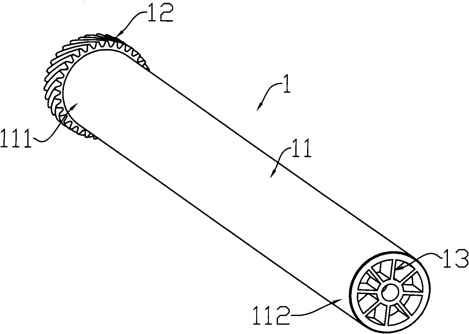
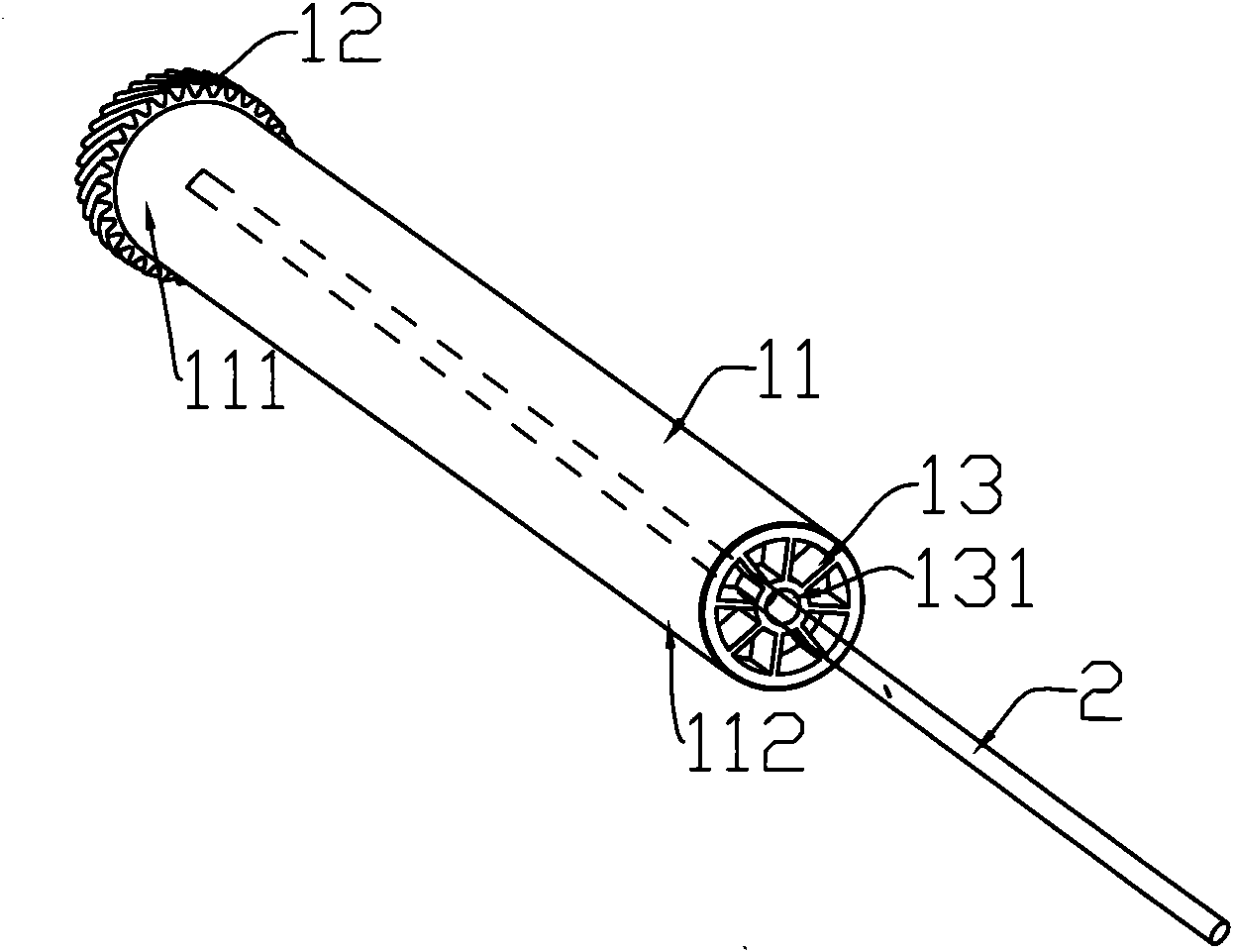
[0023] figure 1 is a structural schematic diagram of a recycled photosensitive drum, which is referred to as the first photosensitive drum 1 hereinafter. The first photosensitive drum 1 includes a drum body 11 , a drum gear 12 mounted on one end 111 of the drum body 11 and a component 13 mounted on the other end 112 of the drum body 11 . The drum body of the first type photosensitive drum 1 has the same diameter and drum surface characteristics as that of another type of photosensitive drum. For the convenience of description, the other type of photosensitive drum will be referred to as the second type photosensitive drum hereinafter. The structure of drum gear 2 and component 2 of the second photosensitive drum is different from that of the first photosensitive drum 1 .

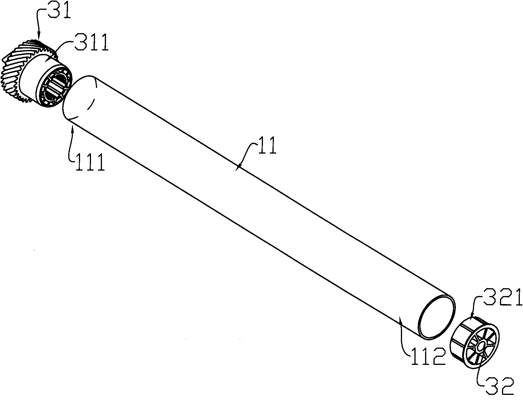
[0024] In order to remanufacture the first type of photosensitive drum 1 into the second type of photosensitive drum, the following methods can be used:

[0025] A. Disassemble the drum gear one 12 and par...

Embodiment 2

[0033] Although the drum body of the first photosensitive drum in this example is the same as the drum body diameter and drum surface characteristics of the second photosensitive drum, the lengths are different. In this case, the Figure 5 As shown, first the end 112 of the mounting part 13 of the drum body 11 of the first photosensitive drum 1 is cut off, so that the drum body 11 of the first photosensitive drum 1 has the same length as the drum body of the second photosensitive drum , and then remove the drum gear one 12 installed on the other end 111 of the drum body 11 of the first photosensitive drum 1, and then install the drum gear two and part two suitable for the second photosensitive drum on the cut-off drum body ends.

[0034] Of course, when the drum body 11 is shortened, one end 111 of the belt drum gear one 12 can also be cut off earlier, and then the part one 13 is pulled down, which has no essential difference.

[0035] Wherein, the dismantling method of drum...


PUM


Abstract

The invention discloses a method for remanufacturing a photosensitive drum into another photosensitive drum, which comprises the following steps: A, disassembling a first drum gear arranged at one end of a drum body of the photosensitive drum and a first component arranged at the other end of the drum body of the photosensitive drum; and B, respectively assembling a second drum gear suitable for anther photosensitive drum and a second component at two ends of the drum body. The method can improve the flexibility of production of consumables regeneration enterprises and avoid resource waste.

Description

technical field [0001] The invention relates to a method for remanufacturing a photosensitive drum used in a toner box, in particular to a method for remaking a recycled photosensitive drum into another photosensitive drum. Background technique [0002] Printers, copiers, fax machines, etc. are commonly used office equipment. They charge and expose the photosensitive drum through the charging roller to form an electrostatic latent image, and then transfer the toner to the electrostatic latent image part on the photosensitive drum through the developing roller. The toner image After being sent to the paper for heating and setting, the printed text image is finally formed. Considering the factors of cost reduction and environmental protection, it has become more and more important to recycle the used product bodies, imaging units, parts, etc. of image forming devices such as copiers, printers, and facsimiles, so as to regenerate them for reuse. [0003] The photosensitive dru...

Claims


Application Information

Patent Timeline
Patent Type & Authority Applications(China)
IPC IPC(8): G03G21/00G03G15/00B09B3/00
Inventor 李杰邓春华
Owner PRINT RITE UNICORN IMAGE PROD CO LTD
Why Eureka
Try Eureka