New type high-power LED driving power source
A LED drive, high-power technology, applied in the field of constant current controllers and drivers, can solve the problems of no dimming interface and low efficiency, and achieve the effects of prolonging service life, low temperature rise, and improving safety and reliability
- Summary
- Abstract
- Description
- Claims
- Application Information
AI Technical Summary
Problems solved by technology
Method used
Image

Examples
Embodiment Construction
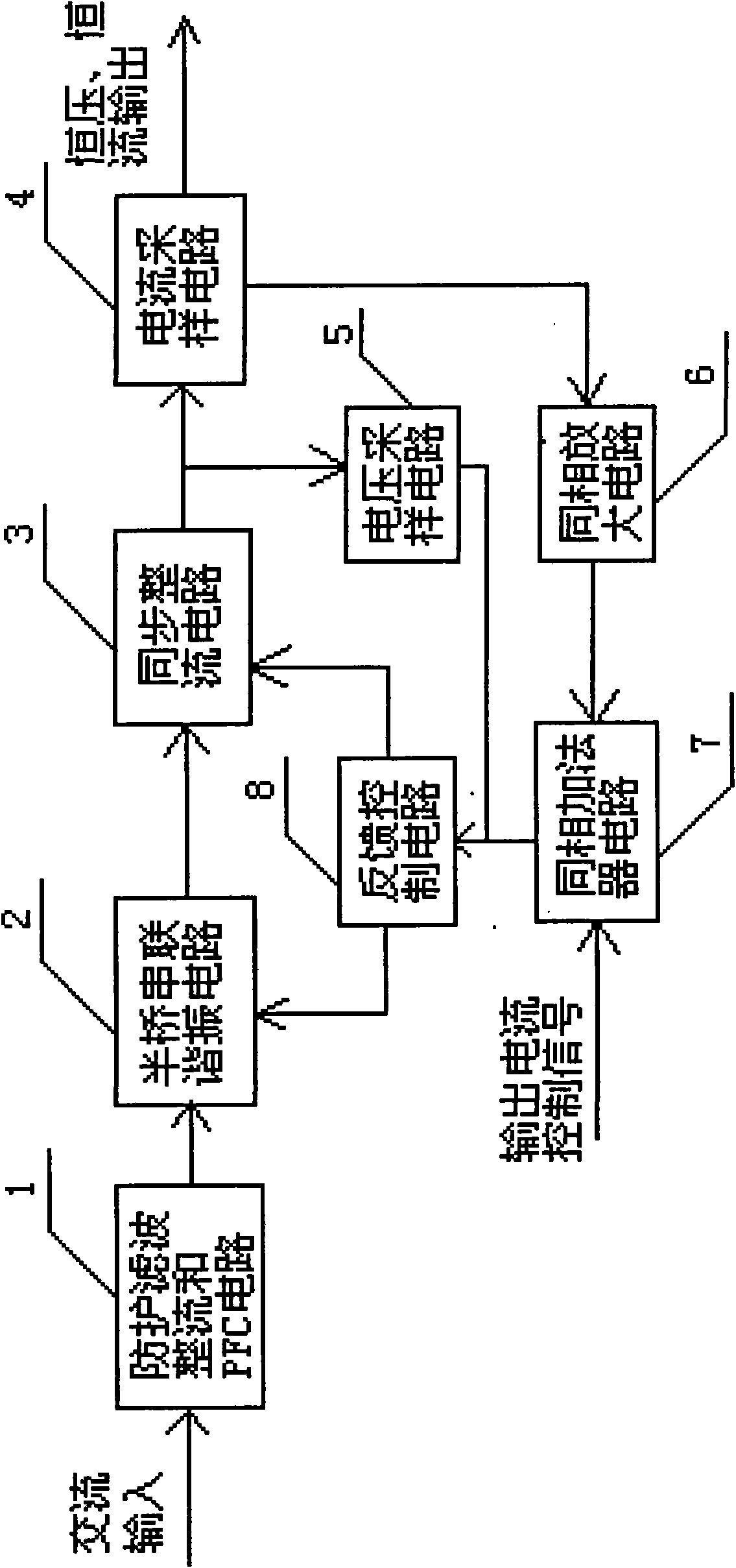
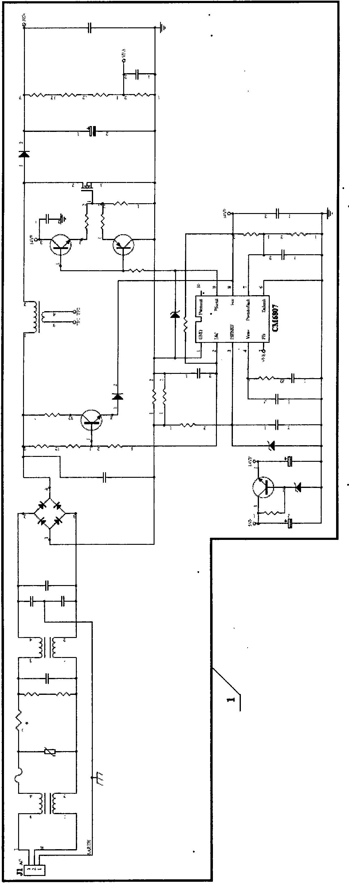
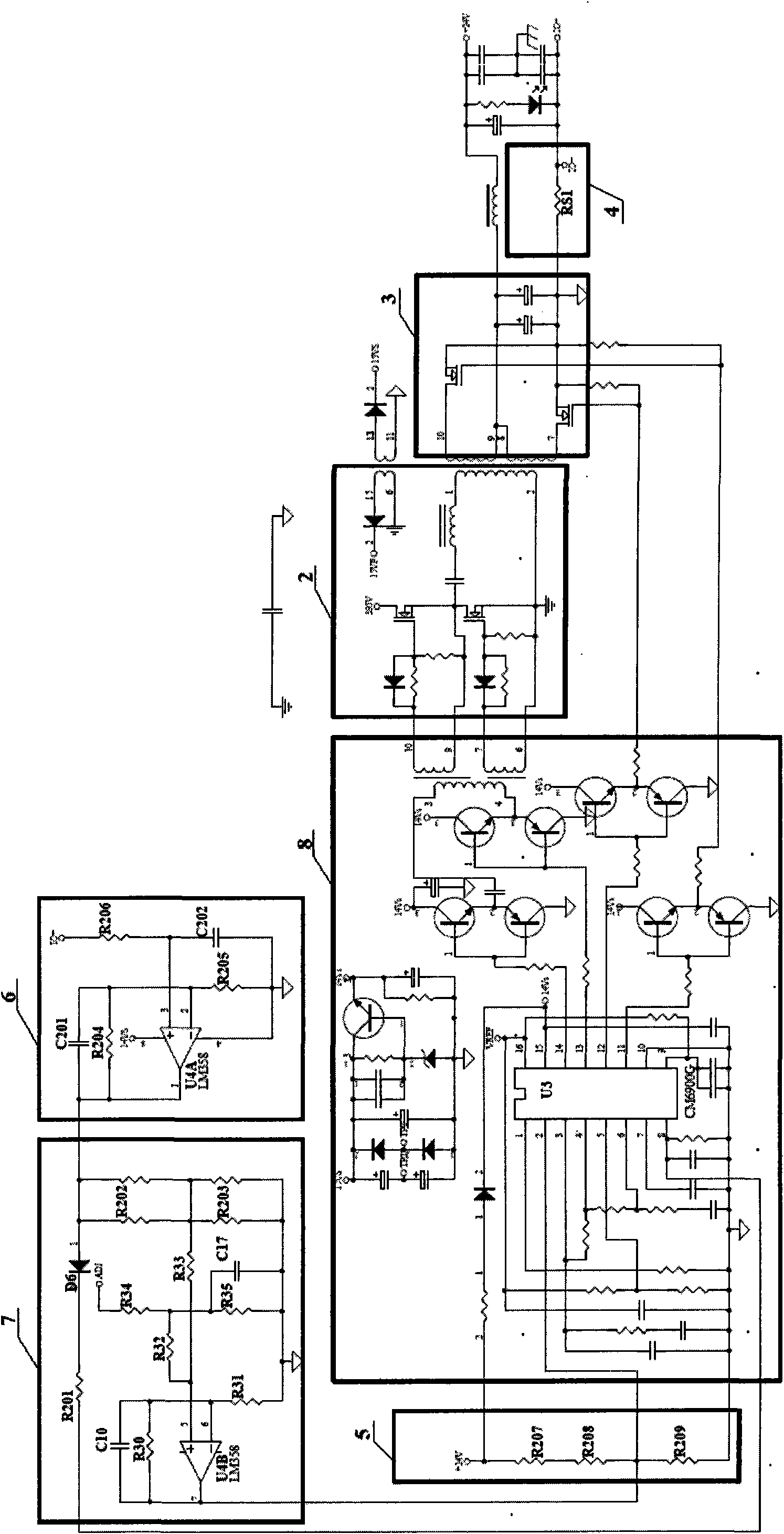
[0016] Structural references for the present invention figure 1 , figure 2 , image 3 , which includes a protective filter rectification PFC circuit 1, a half-bridge series resonant circuit 2, a synchronous rectification circuit 3, a current sampling circuit 4, a voltage sampling circuit 5, a non-inverting amplifier circuit 6, a non-inverting adder circuit 7 and a feedback control circuit 8.
[0017] The input end of the protective filter rectification and PFC circuit 1 is connected to an external AC input power supply, the output end is connected to the half-bridge series resonant circuit 2, the output end of the half-bridge series resonant circuit 2 is connected to the synchronous rectification circuit 3, and the output end of the synchronous rectification circuit 3 is connected to the voltage sampling Circuit 5 and current sampling circuit 4;
[0018] The current sampling circuit 4 is composed of a current sampling element RS1, the input terminal of RS1 is connected to t...
PUM
 Abstract
Description
Claims
Application Information