Parking brake device of a vehicle with emergency release function and method for operating such a parking brake device

A technology of braking device and parking brake, applied in the direction of brake, reservoir arrangement, braking safety system, etc., can solve the problem that the parking brake can no longer be released, the releasability of the parking brake has not been fully solved, etc. problem, to achieve the effect of reducing the vision is not wide and reducing the danger of staying still

Active Publication Date: 2010-01-06
WABCO EURO BVBA SPRL
View PDF2 Cites 34 Cited by
  • Summary
  • Abstract
  • Description
  • Claims
  • Application Information

AI Technical Summary

Problems solved by technology

[0011] Thus, in known parking brake arrangements with an emergency release function, there is a rather high possibility that, in the event of a pipe rupture in the first parking brake circuit, despite the emergency release function, the The parking brake still can no longer be released
Thus far the releasability of the parking brake in emergency release situations has not been adequately addressed

Method used


Image

  • Parking brake device of a vehicle with emergency release function and method for operating such a parking brake device
  • Parking brake device of a vehicle with emergency release function and method for operating such a parking brake device
  • Parking brake device of a vehicle with emergency release function and method for operating such a parking brake device

Examples


Embodiment Construction

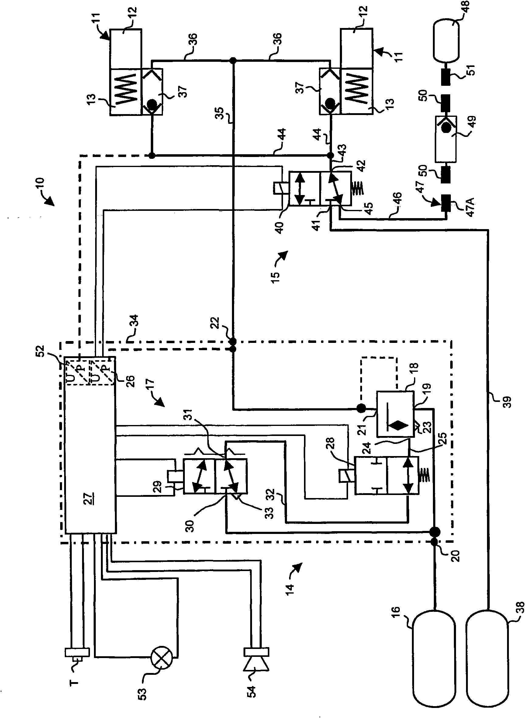
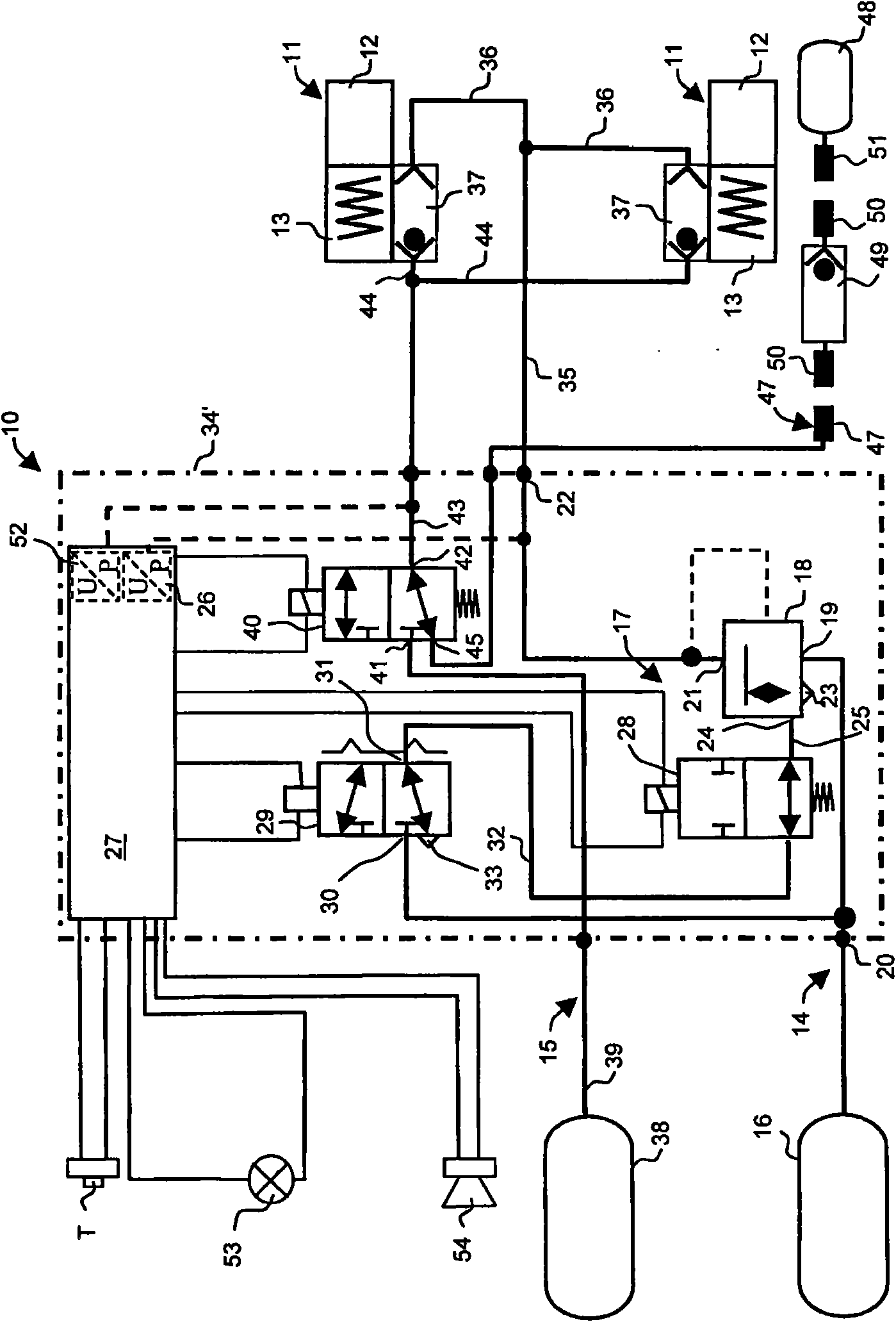
[0022] figure 1 A parking brake device 10 for a motor vehicle, in particular a commercial vehicle, preferably a bus, is shown schematically.

[0023] In the exemplary embodiment shown, the parking brake device 10 comprises two spring-charged brake cylinders 11 designed as combined spring-charged cylinders / diaphragm brake cylinders. In addition to the function of a diaphragm brake cylinder, this combined brake cylinder additionally has a spring energy storage function. The spring-loaded brake cylinders 11 each comprise a diaphragm part 12 which is connected pneumatically to a service brake system (not shown) and to which a specific braking pressure can be applied. Furthermore, the spring-charged brake cylinders 11 each include a spring-loaded part 13 which is pneumatically separated from the diaphragm part 12 and which can be supplied with compressed air via a separate compressed-air line.

[0024] Each spring energy store 13 performs a spring energy storage function in that ...


PUM


Abstract

The invention relates to a parking brake device (10) of a vehicle, especially a utility vehicle, with an emergency release function, comprising at least one spring brake cylinder (11) for releasing or engaging a parking brake and a first electro-pneumatic parking brake circuit (14) with a first compressed air storage tank (16) and a first valve control device (17) for aerating or deaerating the spring brake cylinder (11). A second electro-pneumatic parking brake circuit (15) for emergency release of the parking brake in the event of failure of the first parking brake circuit (14) is further provided, which comprises a second compressed air storage tank (38) and a second valve control device (40) for aerating the spring brake cylinder (11) in the event of an emergency release. The second valve control device (40) comprises an aeration connection (41) connected to the second compressed air storage tank (38), a deaeration connection (45) that can be connected to the atmosphere and a third connection (42) that can be connected to the spring brake cylinder (11). According to a first aspect of the invention and in order to improve the releasability of the parking brake device in the event of an emergency release, the deaeration connection (45) of the second valve control device (40) is connected to a compressed air line (46) which terminates at an outer region of the vehicle, wherein compressed air can be fed in this compressed air line (46) from an external compressed air source (48) to the spring brake cylinder (11) via the deaeration connection (45) and the third connection (42) of the second valve control device (40).

Description

technical field [0001] The invention relates to a parking brake device for a vehicle, especially a commercial vehicle. The parking brake device has an emergency release function and is used for emergency release of the parking brake. Furthermore, the invention relates to a method for operating such a parking brake system. Background technique [0002] Known parking brakes used in particular in commercial vehicles (which are also called parking brakes) have spring-charged brake cylinders which are charged in order to release the parking brake, and is bled to engage the parking brake. A (first) parking brake circuit is provided for this purpose. [0003] In the event of a leak in the compressed air line to the spring-charged brake cylinder, the spring-charged brake cylinder is vented and the parking brake is engaged. Due to this leakage, however, the spring-loaded brake cylinder can no longer be charged, so that the parking brake is no longer released. In this situation, i...

Claims


Application Information

Patent Timeline
Patent Type & Authority Applications(China)
IPC IPC(8): B60T17/06B60T17/18
CPCB60T17/06B60T17/18B60T13/04B60T13/588B60T13/683
Inventor 乌韦·本施亨宁·弗尔斯特伯恩德-约阿希姆·基尔维尔弗里德·门泽尔哈特穆特·罗森达尔奥特马尔·施特鲁韦伯恩德-约阿希姆·基尔
Owner WABCO EURO BVBA SPRL
Why Eureka
Try Eureka