Rotary adjusting damper

A technology of rotary adjustment and damper, used in door/window fittings, shock absorbers, switches with brakes, etc., can solve the problems of unstable torque accuracy, deterioration of assembly, unstable torque, etc., and achieve stable torque Accuracy, easy assembly, leak prevention effect

Active Publication Date: 2008-07-02
NIFCO INC
View PDF8 Cites 0 Cited by
  • Summary
  • Abstract
  • Description
  • Claims
  • Application Information

AI Technical Summary

Problems solved by technology

[0011] However, if there is no opening (hole) for communicating the storage part with the atmosphere, the air remains in the storage part, which deteriorates the assemblability, and the torque deviation occurs due to the air being mixed with the viscous fluid, which makes the torque accuracy unstable (generated unstable torque)

Method used


Image

  • Rotary adjusting damper
  • Rotary adjusting damper
  • Rotary adjusting damper

Examples


Embodiment Construction

[0058] Hereinafter, embodiments of the present invention will be described with reference to the drawings.

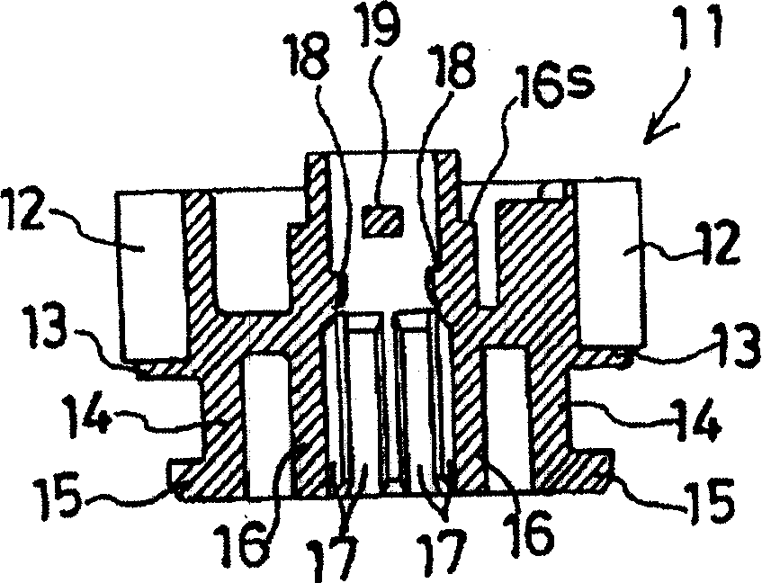
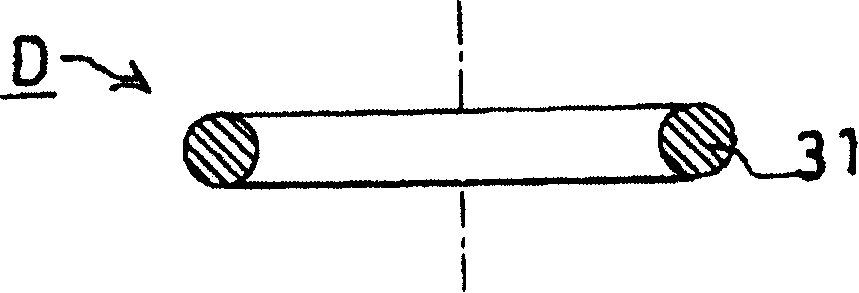
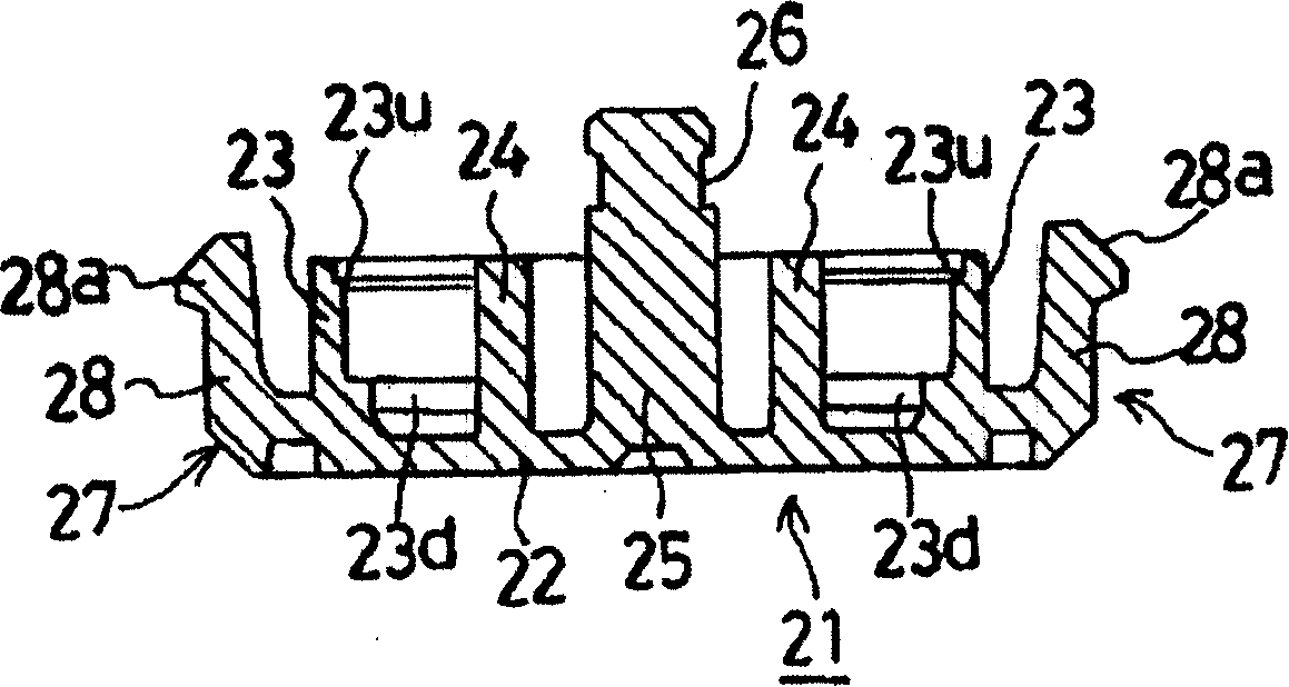
[0059] Figure 1a-1c It is an exploded main sectional view of the rotary damper of the first embodiment of the present invention, figure 2 yes Figure 1c A top view of the fixed support member shown, image 3 yes Figure 1a A top view of the driven rotating part shown, Figure 4 is assembled Figure 1a-1c The parts shown are assembled into the main sectional view on the way of rotating the damper, Figure 5 is assembled Figure 1a-1c The parts shown are assembled into a top view on the way of rotating the damper, Figure 6 is assembled Figure 1a-1c The parts shown are assembled into a front view of the state of the rotary damper, Figure 7 is assembled Figure 1a-1c The parts shown are assembled into a top view of the state of rotating the damper, Figure 8 is assembled Figure 1a-1c The bottom view of the parts shown and assembled into the state of rotatin...


PUM


Abstract

This invention provides a rotary damper capable of maintaining the preciseness of constant torque by avoiding trapping of useless air in a compartment of the damper and facilitating the assembling without allowing air to mix with a viscous fluid. The rotary damper (D) comprises a driven rotary member (11) and a fix-supporting member (21), and a viscous fluid (51) for braking the relative rotation between the two members. The rotary damper (D) has a ring shaped compartment (41) formed between the driven rotary member (11) and the fix-supporting member (21) for containing the viscous fluid (51). An O ring (31) is provided in an outer periphery of the compartment (41) to seal the driven rotary member (11) and the fix-supporting member (21) while allowing a relative rotation therebetween. The driven rotary member (11) is provided with an inner cylindrical wall (16) having an opening for communicating a central portion of the compartment (41) with atmosphere, the opening in the inner cylindrical wall (16) being closed after assembling the driven rotary member (11) and the fix-supporting member (21).

Description

technical field [0001] The present invention relates to a rotary damper in which a driven rotating member is braked by viscous resistance of a viscous fluid, and a fixed support member that rotatably supports the driven member rotates relative to each other. Background technique [0002] As the above-mentioned rotary damper, for example, it is known to be formed by: a driven rotating member integrally provided with a driven rotating part engaged with a driving member such as a gear or a rack; The ring-shaped storage part between the fixed support part and the driven rotating part, the driven rotating part and the fixed support part can relatively rotate to block the sealing mechanism at the outer peripheral end of the storage part, and is stored in the storage part and used for making It is composed of a viscous fluid that is driven by a rotating part and a fixed support part that rotates relative to each other. [0003] [Patent Document 1] Utility Model Registration No. 26...

Claims


Application Information

Patent Timeline
Patent Type & Authority Patents(China)
IPC IPC(8): F16F9/12
CPCE05F3/14F16F9/12F16F9/145F16F9/36F16F9/44
Inventor 林见冈林俊辅
Owner NIFCO INC
Why Eureka
Try Eureka